I guess I was just thinking to much like a consumer designer than a diy'er. Sy, wasn't thinking outside the box on that one was I! Somebody want to explain the advantage of much more gain in an earlier stage, why you would want to do that? Would you then lower the gain in the amplifier stage or just pass it on through. Wouldn't you still have a limit on the dissipation factor in the output devices in the amplifier?
The idea is basically the same as Nelson Pass's F4, but using Doug's "optimizing conventional technology" approach. Unity gain in the power stage, so presumably very high feedback and low distortion. Lin amps, as they sit, would (I think) be difficult to make unity gain stable, but perhaps a better engineer than I can do it.
The fact that I have a line stage with 26dB of gain, 30+ volt output capability, and low output impedance collecting dust on a shelf isn't motivating my question at all. Nossir! This is purely unselfish!
The fact that I have a line stage with 26dB of gain, 30+ volt output capability, and low output impedance collecting dust on a shelf isn't motivating my question at all. Nossir! This is purely unselfish!
Well, if I send 1V down a line versus 20V, and I am picking up the same noise along the way, where do I get a better system S/N? Likewise, if I can isolate the high current power supply from the low level electronics (which only require a few tens of milliamps) by several meters, I might expect a better noise performance with less worry about hum pickup. Further, if the preamp noise is constant and the rated output is 26dB greater, that also translates to a S/N improvement.
Admittedly, these are fine hairs to split, but if we want to worry about tiny amounts of distortion (and Doug will be the first to tell you that we're dealing with levels far below audibility), we might take a similar attitude about noise.
Admittedly, these are fine hairs to split, but if we want to worry about tiny amounts of distortion (and Doug will be the first to tell you that we're dealing with levels far below audibility), we might take a similar attitude about noise.
They are certainly not identical. The two methods do quite different things in quite different ways. I'd be interested in a link to wherever it is that someone claims to have proved they are the same. Should be amusing...
I think the more accepted name for TMC is Output-Inclusive Compensation. May not roll off the tongue, but it does at least describe what it does.
Doug,
I may not be the best historian in the world, but I frankly never knew about properly-applied TMC until Edmond popularized it with the term "Transitional Miller Compensation", perfectly capturing the behavior where the compensation action transitions from Miller compensation around the output stage to conventional Miller compensation as frequency increases.
This, in contrast to Ed Cherry's compensation that can be termed output-inclusive compensation, as it is essentially Miller compensation that essentially includes the output stage at all frequencies.
I am not aware of many people at all that consider output-inclusive compensation as a more accepted than the term TMC. Look in that very important thread and see how many people asserted that it should be called output inclusive compensation.
Cheers,
Bob
This, in contrast to Ed Cherry's compensation that can be termed output-inclusive compensation, as it is essentially Miller compensation that essentially includes the output stage at all frequencies.
Hi Bob
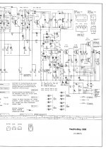
In fact it predates largely Cherry s article and Baxandall findings ,
see below the amp part of Grundig Yachtboy portable radio circa 1967 ,
C64 is the miller cap and goes from the amp output to the VAS input ,
effectively enclosing the power stage.
Agree that TMC is not exactly the same beast.
Attachments
I do think the book is perfect...also Self is perfect
There's anything to include or exclude.... maybe an update because advances of technology..but only that.
It is a book about audio..not an encyclopedia of audio.
There's much more there than we, diyers, need to know.
I do not think the name encyclopedia is not written into the book face frontal page.
If he join all his books together..then we have the encyclopedia.
I have readed 4 of his books... i doubt too many people did that.
- Small signal audio design
- Design of active crossovers
- Self on audio
- The Design handbook
If we tweak something, already very nearby perfection, we can mess with the whole thing.
To join all books together...the ones i have readed and others i have not..all them in a single "bible" of audio...this may be good...using thinner paper pages to reduce; weight, cost and size, will reduce price compared to the many books sold in separate.
Something alike Tremaine did in his audio encyclopedia..but he started at 1920's technology and finished with seventies technology (the one i had).... something more modern... starting in the eighties may be interesting for all of us.
Original Tremaine encyclopedia was consisted in two big books...1000 thin pages each one if i can remember...you see he reduced to a single volume..so..my idea is not that bad.
Carlos
Attachments

Last edited:
And even easier with ICs....
Old school Akai PR A04 preamp manage an healthy 20V RMS
output using Toshiba s TA7322.
Doesn't sound too healthy to me. 20 Vrms would blow up a lot if input stages running on more conventional +/-15V rails.
Some of my early preamp designs had +/-24V rails and could put out quite hefty voltages, but I no longer think this is a clever idea. You need to be very careful with switch-on transients and the like.
Hi
Is it possible to include information (circuits, comparisons, comments) on soft start and protection systems. These are rarely if ever included in text books.
Don
Already in the 5th edition.
Doug, I think many readers would be grateful for a discussion of PCB layout, with illustrations. A few different DS-approved ways to place the OPS transistors on a 1-layer PCB, and route the high current tracks to them. Discussion of those layouts with pros and cons.
A few more DS-approved ways to place the OPS transistors on a 2-layer PCB and route the high current tracks. Discussion. Philosophy and economics of 2-layer vs 1-layer construction. (A pet "issue" of mine: should one, or should one not, trust a component's leg/lead to provide a reliable "via" between top and bottom layer in a thru-hole board? How about when the component body is larger than the solder footprint (e.g. 10mm electrolytic caps) so the top-side solder joint is not inspectable or touch-up-solderable? Should one strive to have N>1 parallel connections each time a net switches from bottom to top?)
Discussion of partitioning an amplifier among more than one board. Power supply on its own board? On two boards? Why or why not? Muting relays and soft-start circuitry on the same board as housekeeping microcontroller?
Speaking of microcontrollers, perhaps you have some suggestions about how to include digital circuitry inside an analog power amp chassis, with minimum noise contamination and hopefully minimum exta cost. Including perhaps some wisdom born of bitter experience, on the 1 good way and the 4 bad ways, to interface to a medium resolution LCD graphical display on the front panel of an amplifier.
Finally I'd enjoy reading your thoughts & advice about meeting the sub-500 milliwatt standby, energy saver speifications. What are the good ideas, what are the lousy ideas, what are the crazy ideas. Particularly for devices that can be powered-up via IR remote control.
Thanks for reading.
meeting the sub-500 milliwatt standby
TRANSF 5VAC .5A 2.5VA WORLD SERIES
and a LDO for 3.3V logic. You could sub a cheap DC/DC for this to reduce power even more.
The 3.3V logic does not use much power in standby, so ckts can be put to sleep and only the wake up logic needs to be active.
Use a relay such as Panasonic ALE1PB05 to switch on the main PS. I looked at Triacs but they are lossy at high currents. Relays are reliable enough for this application.
The expensive way is a off-line switch mode PS for the auxiliary 3.3V
Yet another option, Fairchild FSAR001BNY
Rick
I think that I can answer this question, since I have been doing it of late.The simple cheap way is to make a small auxiliary PS, using a small filament transformer, such as Triad VPP10-250 from Digi-key. It is:Finally I'd enjoy reading your thoughts & advice about meeting the sub-500 milliwatt standby, energy saver speifications. What are the good ideas, what are the lousy ideas, what are the crazy ideas. Particularly for devices that can be powered-up via IR remote control.
TRANSF 5VAC .5A 2.5VA WORLD SERIES
and a LDO for 3.3V logic. You could sub a cheap DC/DC for this to reduce power even more.
The 3.3V logic does not use much power in standby, so ckts can be put to sleep and only the wake up logic needs to be active.
Use a relay such as Panasonic ALE1PB05 to switch on the main PS. I looked at Triacs but they are lossy at high currents. Relays are reliable enough for this application.
The expensive way is a off-line switch mode PS for the auxiliary 3.3V
Yet another option, Fairchild FSAR001BNY
Rick
Last edited:
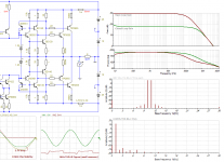
I guess that from your earlier answer that Edition 6 will have more information on maximising the NFB. Some measurement results like a traditional Bode Plot for the open loop gain and phase of a typical blamelesss amplifier would be interesting though possibly difficult.
Another difficult question is how close to instability can an amplifier operate? One moment Ok, next toast.
Another difficult question is how close to instability can an amplifier operate? One moment Ok, next toast.
Doug,
I may not be the best historian in the world, but I frankly never knew about properly-applied TMC until Edmond popularized it with the term "Transitional Miller Compensation", perfectly capturing the behavior where the compensation action transitions from Miller compensation around the output stage to conventional Miller compensation as frequency increases.
This, in contrast to Ed Cherry's compensation that can be termed output-inclusive compensation, as it is essentially Miller compensation that essentially includes the output stage at all frequencies.
Cheers, Bob
Hello Bob
Must say I don't much care for the term "Transitional Miller Compensation" as it gives no clue as to what is transitioning to what. "Output-Inclusive Compensation" does at least say what it does. Still, a minor matter.
I'd be most interested to know where Edmond learnt about the technique. It can be instructive to trace these ideas back as far as possible.
Cherry did indeed advocate putting the output stage inside the Miller loop at all times- IMHO, not a very helpful suggestion as in my experience it can never be made stable.
The Yacht-Boy schematic is most interesting, but it is notable that the output stage is just two devices without a driver stage. I imagine that's why it was stable. It would be interesting to find out if it was done in an informed fashion or by accident.
Hi Doug,
Two reasons I chose to use the term TMC in my book. First, TMC was popularized by Edmond and virtually everyone on this forum was accustomed to using it. Second, it seemed like a very logical term - it is Miller compensation and its tap point transitions from main output to VAS output. The fact that to the uninformed what is transitioning is the price we pay for acronyms that are efficient and not nearly sentences.
Also, the term output-inclusive compensation was used in your 5th edition to describe the Cherry arrangement, so to now use it as well for TMC adds confusion.
Edmond told me that he believed the arrangement used in TMC was from Baxandall. I believe that Baxandall did not publish it and probably regarded it only as a curiosity, and perhaps did not relize the power of the technique when properly applied with good ratios of C1 to C2. For this reason, I believe that Edmond deserves the credit for popularizing it and properly articulating how it works and what kinds of C1/C2 values are well-suited to the technique. If he deserves this credit, then I think he deserves to name it.
Like you, I've been in this business for 40 years and never heard of it or was aware of it. I learned it from Edmond, so I give him the credit. On a side note, TMC is the only other technique than Hawksford Error Correction that I know of that can deliver nearly the kind of performance that HEC does. At least the kind of HEC I used in 1983 in My MOSFET power amplifier with error correction that achieved <0.001% THD at 20kHz.
BTW, the origins of TPC are interesting as well. In the early to mid 70's at Bell Labs we called it "T" compensation. Two of my collegues, Jimmy Tow and Lee Thomas, of BIQUAD fame, recognized that they needed op amps with higher in-band open-loop gain to make active filters with the performance we needed. In response, the organization I was in at the time (not me, I was working on IC PLLs) designed IC op amps with T compensation. They were then used all over the place in the Bell System. To the best of my knowledge, T compensation (TPC) was first developed at Bell Labs, probably circa 1973.
Cheers,
Bob
Hello Bob
Must say I don't much care for the term "Transitional Miller Compensation" as it gives no clue as to what is transitioning to what. "Output-Inclusive Compensation" does at least say what it does. Still, a minor matter.
I'd be most interested to know where Edmond learnt about the technique. It can be instructive to trace these ideas back as far as possible.
Cherry did indeed advocate putting the output stage inside the Miller loop at all times- IMHO, not a very helpful suggestion as in my experience it can never be made stable.
The Yacht-Boy schematic is most interesting, but it is notable that the output stage is just two devices without a driver stage. I imagine that's why it was stable. It would be interesting to find out if it was done in an informed fashion or by accident.
Hello Douglas,
Isn't this TMC in the Baxandall papers in your home page??
http://www.douglas-self.com/ampins/baxandall/Baxandall papers 34.jpg
BR Damir
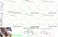
I think TMC arrangement help to minimize output overloading at high feedback system in BJT output. Compensators are used widely and so many type of them
Local dynamic compensation like Vgs compensation in my mosfet amp or in cascoded BJT to keep constant Ic at input stage are more useful for better linearity.
Local dynamic compensation like Vgs compensation in my mosfet amp or in cascoded BJT to keep constant Ic at input stage are more useful for better linearity.
Attachments
- Status
- This old topic is closed. If you want to reopen this topic, contact a moderator using the "Report Post" button.
- Home
- Amplifiers
- Solid State
- Audio Power Amplifier Design book- Douglas Self wants your opinions