jxd - TPC gain peak, square wave overshoot is not a direct indication of (in)stability
the Cordell Book thread discussion has several analysis of this - you can prefilter, adjust TPC values, add a lead network
a small shunt or bridging C can reduce loop gain peaking - if that matters
if the TPC overshoot worries you you shouldn't feel any better about TMC - the stabilty issues are the same as TPC, its just that the Global loop response looks more familiar
but you pay the same price in stability margin for added distortion reduction with both techniques - no free lunch
I see no reason from my reading of psychoacoustics or knowlege of audio transducers to think we need to worry about TPC settling microsecond scale settling "tail" - all audio signal are unavoidably bandlimited in mics, speakers with 10s of us time constants, usually 2nd order
Last edited:
in the Cordell Book thread I showed several ways to test loop gain that give a fairly accurate result for TMC - you have to measure inside both loops enclosing the output Q
http://www.diyaudio.com/forums/soli...s-self-wants-your-opinions-8.html#post3402379
the square wave response for TMC doesn't indicate stablity margin as we are used to with simple dominant pole Miller compensated amps - a reason for warnings against using TMC if you don't understand stability evaluation at a pro EE level, would be "nervous" using 2-pole - they are similarly complcated, TMC easliy measured incorrectly
It's not that complicate.
Actually, I came out this type compensation by my own one day, and then I found the same structure had already existed for a long time out there.
The worst scenario of TMC is at very high frequency. At that time, you can see a resistor crosses between input of OUTPUT STAGE and output of OUTPUT STAGE. Because the resistor there also consume some current from VAS, it actually slightly reduces the open loop gain. How much it reduces depends on the value of the resistor. The effect is rather minimal, because there won't be huge voltage crossing there.(I keep transitional frequency about 1.59MHz, when output device still has the control of output voltage.)
jxd - TPC gain peak, square wave overshoot is not a direct indication of (in)stability
the Cordell Book thread discussion has several analysis of this - you can prefilter, adjust TPC values, add a lead network
a small shunt or bridging C can reduce loop gain peaking - if that matters
if the TPC overshoot worries you you shouldn't feel any better about TMC - the stabilty issues are the same as TPC, its just that the Global loop response looks more familiar
but you pay the same price in stability margin for added distortion reduction with both techniques - no free lunch
I see no reason from my reading of psychoacoustics or knowlege of audio transducers to think we need to worry about TPC settling microsecond scale settling "tail" - all audio signal are unavoidably bandlimited in mics, speakers with 10s of us time constants, usually 2nd order
Yes, I know that doesn't mean unstable.
I just need to take some time to learn how to tame TPC.
I want to get a good result before put it into real.
e.g. 10% overshoot. 1us settling time.
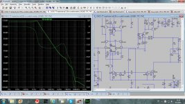
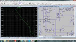
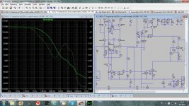
Here is how I try to simulate TPC-TMC combination.
First picture TPC only with no capacitive brigde over TPC (C22)
Second picture TPC only with cap bridge(no overshooting). This small cap could be just parasitic.
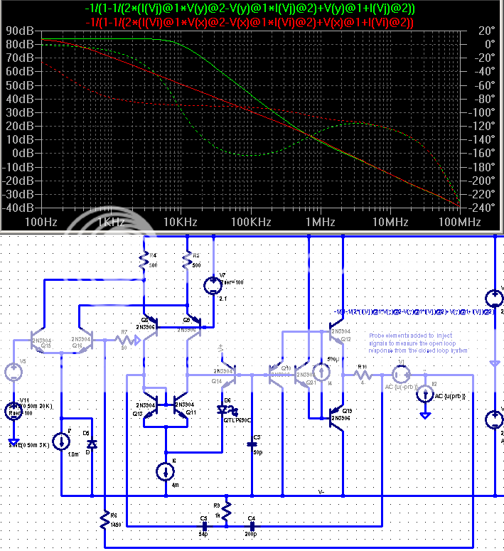
Third picture TPC TMC simulation, Middlbrook probe between output and TMC resistot(R30).
I am not sure this approach is good enough I could be completely out of track.
To small phase margin is not for the moment od any concern as this simulation is here just an example.
BR Damir
First picture TPC only with no capacitive brigde over TPC (C22)
Second picture TPC only with cap bridge(no overshooting). This small cap could be just parasitic.
Third picture TPC TMC simulation, Middlbrook probe between output and TMC resistot(R30).
I am not sure this approach is good enough I could be completely out of track.
To small phase margin is not for the moment od any concern as this simulation is here just an example.
BR Damir
Attachments
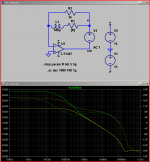
Here is how I try to simulate TPC-TMC combination.
First picture TPC only with no capacitive brigde over TPC (C22)
Second picture TPC only with cap bridge(no overshooting). This small cap could be just parasitic.
Third picture TPC TMC simulation, Middlbrook probe between output and TMC resistot(R30).
I am not sure this approach is good enough I could be completely out of track.
To small phase margin is not for the moment od any concern as this simulation is here just an example.
BR Damir
All three amps are a disaster waiting to happen.
They are all only conditionally stable, meaning there are closed loop gains at which these amps are not stable (that is, where the phase hits 180 degrees before the ULGF). While this is unlikely to happen during normal operation (although I would carefully check the stability when the output approaches the rails), during power up and power down such amps do have the nasty habit to burst into oscillations. Depending on the power supply and how lucky you are, it could be anywhere between one day and one year until such amps will blow in the user's face.
As a rule of thumb, audio power amplifiers should be unconditionally stable, with a healthy margin of at least 20-30 degrees at all frequencies.
A very useful set of hints are Scott Wurcer's recommendations for grounding & decoupling in the AD797 datasheet.
Yes but the AD797 is a single gain stage VFA with shunt compensation to ground (well virtually ground, Vcc/Vee) like a CFA so it has to be inferior.

thats OK Scott - we can still 2-pole (de)compensate - ends up looking like TPC
http://www.diyaudio.com/forums/solid-state/123613-class-biasing-ad797-6.html#post1525757
http://www.diyaudio.com/forums/solid-state/123613-class-biasing-ad797-6.html#post1525757
Last edited:
just for entertainment value - CFA "TPC" - inductors are usually avoided in small signal audio - but are used in J990 discrete op amp
(shows a little lower gain with the Middlebrook/Tian loopgain probe - but much harder to show stepped component effects)
(shows a little lower gain with the Middlebrook/Tian loopgain probe - but much harder to show stepped component effects)
Attachments
Last edited:
RFI-EMI
I would be glad to read a paragraph about the intrusion and the avoidance of RFI-EMIs. It has been said that input stages having FETs or very linear circuits are less vulnerable to them.
Quite interesting, my 1994 EW blameless boards have no low-pass filter and the base of the non-inverting input is connected through a DC decoupling input capacitor to the RCA jack via 8 cm of twisted wires. I think there is a capacitor of a few pF across the feedback resistor connected to the output.
Despite the lack of particular precautions, this stereo amp does not suffer from audible clicks induced by an old fridge which is my main source of RFI and which produced nasty noises with some older designs having a low current in the single bipolar input stage.
The 2x3 mA bipolar differential pair, each with a 100 Ohm degenerating resistor, seems to be an input stage very resistant to radio frequencies parasitics.
Yes but the AD797 is a single gain stage VFA with shunt compensation to ground (well virtually ground, Vcc/Vee) like a CFA so it has to be inferior.
LOL
RFI-EMI
I would be glad to read a paragraph about the intrusion and the avoidance of RFI-EMIs. It has been said that input stages having FETs or very linear circuits are less vulnerable to them.
Quite interesting, my 1994 EW blameless boards have no low-pass filter and the base of the non-inverting input is connected through a DC decoupling input capacitor to the RCA jack via 8 cm of twisted wires. I think there is a capacitor of a few pF across the feedback resistor connected to the output.
Despite the lack of particular precautions, this stereo amp does not suffer from audible clicks induced by an old fridge which is my main source of RFI and which produced nasty noises with some older designs having a low current in the single bipolar input stage.
The 2x3 mA bipolar differential pair, each with a 100 Ohm degenerating resistor, seems to be an input stage very resistant to radio frequencies parasitics.
Interesting forr. I run both my current VFA designs LTP's at 10 mA (so 5 mA per side). The older design has 100 Ohms of degeneration (IIRC) and the newer one 47 Ohms. I have also had no problems with RF - very clean. I think for discrete designs using BIP inputs, high LTP current and/or degeneration solves the RFI issue, as does a JFET input stage. For IC opamps using BIP input stages, I would concede that they probably are more susceptible than JFET input stages to RFI - its a trade off between RFI immunity and power consumption. But, even with BIP IC opamps, an RFI filter on the front end solves the problem. I usually bandwidth limit at 200-500 kHz with a straight RC filter.
thats OK Scott - we can still 2-pole (de)compensate - ends up looking like TPC
If I only knew, I hope folks can forgive me for not at the time having an encyclopedic knowledge of everything that went on in the audio world.
BTW - The final version of our new power op-amp has been taped out, +-20V very high speed and 1A/10W continuous at 85C ambient. I'm not sure but I think the team is negotiating for a custom heat sink (at least I saw a prototype) to offer with it.
Designed to compete with what?BTW - The final version of our new power op-amp has been taped out, +-20V very high speed and 1A/10W continuous at 85C ambient
Designed to compete with what?
That remains an unnecessary detail, there is an application that has nothing to do with audio.
I design (industrial) hifi amplifiers for consumer market since 1970, with LTPs too, so it was not too long a delayApologies for taking so long to reply, but I have been designing amplifiers. With LTPs.
. Please, re-read my post carefully and, please, please, think twice.
Just compare the same OPA in inverting mode VS non inverting to see that distortion is reduced in inverting mode. (and compare the closed loop bandwidth). Why ? Because the signal is passively subtracted, and the distortion of the -input is not added. I thought i was clear.
I'm afraid you confuse the way the long long-tailed pair works for signal (with distortion cancellation) and for feedback where this distortion cancellation has negative effects, *because* we want this distortion to be 100% subtracted, and not canceled before subtraction.
Sad you answered with authority arguments, instead of technical ones, but i'm not impressed, only disappointed, as i said: my post was not aggressive.
Please, can-you explain what you mean by:
? It can be the same in both situations.There is also the VAS operation to be considered..
BTW: if you designed some mixing desk, may-be i had used some of yours ? What were your babies ? I used mainly NEVE, CALREC, and several English and French ones.
Last edited:
All three amps are a disaster waiting to happen.
They are all only conditionally stable, meaning there are closed loop gains at which these amps are not stable (that is, where the phase hits 180 degrees before the ULGF). While this is unlikely to happen during normal operation (although I would carefully check the stability when the output approaches the rails), during power up and power down such amps do have the nasty habit to burst into oscillations. Depending on the power supply and how lucky you are, it could be anywhere between one day and one year until such amps will blow in the user's face.
As a rule of thumb, audio power amplifiers should be unconditionally stable, with a healthy margin of at least 20-30 degrees at all frequencies.
Did you read my text??
I expected some comments the way I simulated those TPC-TMC combination, and not about the amp, it is not meant to be built as a real amp just an exercise.
But way a power amp should be unconditionaly stabe, it not an OP amp or a buffer?
Even some OP amps are not unconditionaly stabe(at the gain of one).
My TT amp with TMC(look in other thread) is not unconditionaly stable and I use it for year in every day listening.
BR Damir
Designed to compete with what?
LT1210 ;-)
re: post #545
Hi Damir,
even if the current circuit is only playground, it would be interesting how a sound evaluation of such a structure would look like.
Apart from the behaviour of the outer-most global loop (btw., I somewhat agree with the remarks of Waly in post #546), we should investigate all loops, here at least the loops around the VAS alone and the loop around VAS+OPS due to TMC.
In your Bode diagrams, I only see results for the global loop.
BR,
Matze
- Status
- This old topic is closed. If you want to reopen this topic, contact a moderator using the "Report Post" button.
- Home
- Amplifiers
- Solid State
- Audio Power Amplifier Design book- Douglas Self wants your opinions