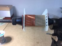
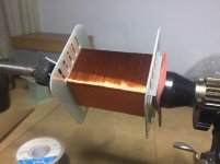
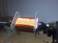
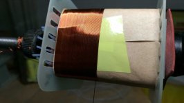
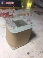
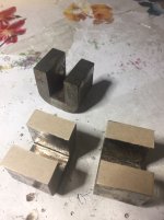
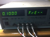
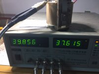
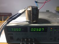
Why the inductance is so low? It should be about 100H according the design
How big is the signal you are applying? Are you sure about the correct air-gap size? Assuming the gap size is right what happens if you clamp the cores tighter?
20 mH leakage inductance is too high. How many primaries have you made?
Assuming the gap size is right what happens if you clamp the cores tighter?
Be careful with tight clamping of amorphous c-cores; it is not difficult to deform the C with too much pressure.
I remember tightening the bands to get more inductance, until the inductance got eventually lower
Silicon steel c-cores are a bit stronger (but therefore less sexy).
1.Input signal is 1V
2.I did not leave air-gap, how to decide the size of air-gap?
3. The prim have 9 sections and 4512 turns in total
If you have 20mH with 9 primaries and 8 secondaries on that core then I can only think that coupling is not good. You should avoid soldering that large piece of wire in the middle of the layer to bring the wire out. It makes layers uneven and difficult to wind. You should choose the wire to end the layer at the end of the bobbin, not in the middle. If the space is not enough choose another wire or another core. This is not a choke!!!
If you use 1V at 100Hz then that's really a minimum (basically DC) inductance. Induction in the core is really tiny. Use lower frequency with 3-5V and it should much better. If you pass DC for inductance measurement then absence of gap might make it saturate. You need some gap to pass 10 mA DC. If you don't have DC for inductance measurements then the problem might be the core itself. I see that the C's don't match really well....
The reason why you don't get 100H might be because that core might not be what you think? I never buy these things from generic vendors without quality control because bad surprises are always around the corner....
Last edited:
Be careful with tight clamping of amorphous c-cores; it is not difficult to deform the C with too much pressure.
I remember tightening the bands to get more inductance, until the inductance got eventually lower. When applying too much pressure the air gap became wider at the outsides because the C "spread it's legs"
.
Silicon steel c-cores are a bit stronger (but therefore less sexy).
Wow! I never imagined such thing could be possible. Although I'm using threaded rods and clamps, but no bands.
It's possible that the clamps we are using are limiting the pressure, because they have some elasticity - thick composite for PCBs.
Thanks, I will add some air gap and test it againIf you have 20mH with 9 primaries and 8 secondaries on that core then I can only think that coupling is not good. <snip>
Of course it needs to be done without damaging the core. A matter of common sense I think.
Common sense is presumed to be present; otherwise don't start winding transformers
It was meant to warn the unexperienced ....
First attempt is failed the wire diameter of Sec is too large
Second time attempt I use 0.13 for Sec
View attachment 634194
View attachment 634195
That's random winding; bad quality power supply transformers are wound that way.
It will not give a good audio transformer.
Try to invest more time and patience to arrange the windings neatly without crossing; that will also save winding space.
Last edited:
I finished the coil, Prim 4512 turns(0.13mm), Sec 1370 turns(0.13mm, 4 groups parallel connection)
View attachment 634958
View attachment 634960
A bad design
You used about halve the available winding space.
The c-core halves are not tightly kept together by the bands, so there can not be a stable fixed airgap.
Check if the c-core halves are correctly paired; it looks odd.
73.5mH is a huge amount of leakage. Do you trust this LCR meter?
A not entirely, but more realistic method of measuring parasitic parameters is to short the secondary, then add a capacitor with a small (10-20nF) value shunting the primary. Then measure the first resonant frequency across the primary. Then measure it again without the capacitor. The later should be the default first resonance and higher than the one with the shunt capacitor
The added capacitor is practically in parallel with the Cp (shunt capacitance), so the resonant frequency will be lowered. To find Cp:
Cp = Cadd / [(Fres1/Fres2)^2 - 1]
Fres1 is the frequency without Cadd
Fres2 is the frequency with Cadd
- Status
- This old topic is closed. If you want to reopen this topic, contact a moderator using the "Report Post" button.
- Home
- Amplifiers
- Tubes / Valves
- Audio Note M10 Clone
