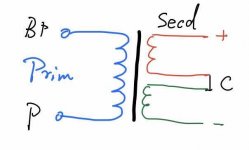
You can go back talking about circuitry and transformers. All I'm saying is that the schematic posted is NOT related to the transformer Peter Qvortrup was talking about.
It doesn't matter really. A preamp transformer with 33:1 turn ratio doesn't make sense regardless of the circuitry. That was the main debate. The transformer they sell apparently has that ratio...actually the lastest has even more step-down ratio.
A preamp transformer with 33:1 turn ratio doesn't make sense regardless of the circuitry.
I agree on that.
By the way, that same circuit that floated around the net prompted someone who built the phono section to question the validity of the schematic as it exhibits severe roll-off and limited bandwidth in simulation and measurement that the schematic "may be a deliberate ploy to prevent copy" or simply has print errors.
It is possible that there are mistakes.
Regarding the line amp, actually there is no info at all about the transformer in the schematics.....unless there is/was another page with a list of components with specs.
The only thing I notice is that it seems it was meant to be used especially in balanced mode. That already changes things because the ratio is 1/2.
Last edited:
Again, there are TWO different beasts of a preamp called M10. The orginal poster jerrylong posted a schematic of a M10 that was designed by Kondo in Japan, clearly dated in the schematic at 1996. Audio Note UK was formed after that and introduced a preamp that also happened to be called M10. Due to legal issue, Audio Note Japan later renamed the company as Kondo. The two preamps are designed by different people, by different companies. The British company is simply called Audio Note UK.
They are different preamps. ANJP uses 6072 & 5687 tubes and ANUK uses 12AU7 & 6463. Jerrylong needs to decide which preamp he wants to clone. He first posted the Japanese schematic and then jazbo8 posted a quote by Peter Qvortrup of ANUK about their M10 transformer. And then Jerrlong posted a discussion in a Chinese forum about ANUK M6 transformer. All of this only adds to the confusion.
You can go back talking about circuitry and transformers. All I'm saying is that the schematic posted is NOT related to the transformer Peter Qvortrup was talking about.
Please return to your regular programming.
Thank you directdriver, you make it clear that I want to clone the M10 of ANJP version, since I can only find the circuit of it but not the UK version, and it used output transformer indeed.
What I want to do is trying to clone the OPT of M10 JP version, peter's quote really confused us, the circuit of M10 UK version is quite different and can not find anywhere.
So let us come back to the JP version and decided the specification of the OPT
28-30K for the single 5687 might be ok. For the paralleled triodes Idc=10mA and impedance will be 14-15K which means about 5:1 turn ratio for a nominal 600R secondary. 110-120H primary inductance at least.
We go always back to the same point.....
Yes, but it is more clear that we are focused on AN JP circuit and I decided not to use 33:1 ratio for the testing coil
Apparently I am missing some essentials here...
First of all: when using a 5687, why not let it do what it can?
Max plate dissipation of 5687 with both units parallel is 7.5 watt; with 120V and 10 mA it will dissipate 1.2 watt. A bit more current would do no harm.
Then, the plate resistance of 5687 with parallel triodes is between 800 and 1000 ohm.
Load impedance of 5k would make enough sense, which can be done with a 3:1 output transformer (600 ohm secondary load).
Mu of 5687 is around 18; with the 5k load and 3:1 transformer you would have a gain of some 4 to 5, perfect for a line amplifier.
Or do you plan to split the cathode resistance at the cost of plate resistance and gain? With a 15k:600R transformer (5:1) you will not have much more gain than 2 to 3.
Just my thoughts....
Last edited:
For the condition that IDC=10mA, the diameter of Prim is 0.13mm will be enough?
Assuming 0.13 mm is the diameter of the copper then you will have 0.75 A/mm^2 current density which is good.
For the condition that IDC=10mA, the diameter of Prim is 0.13mm will be enough?
0.13 mm wire can have 40 mA without getting "hot".
Are you planning to continue asking these basic questions??
It might become a long thread
Sum up the discussion above:
1, forget about 33:1 turn ration(it's for AN_UK)
2, the parallels of 5687 made the impedance of OPT prim Z1=15K, and the second Z2=600R
3, Turn ratio N=(Z1/Z2)^1/2=5:1(for RCA output)=5:0.5+0.5(for XLR output)
3, The inductance of prim L1 will exceed 100H
4, The number of turns of prim N1=4511(with tested coil with 2855 has achieved conductance 41H)
5, The diameter of prim is 0.13
6, The number of turns of second N2=4511/5=902
7, The diameter of second is 0.25, with 4 wires paralleled
If these species are correct and I will design the arrangement of the prim and second
Load impedance of 5k would make enough sense, which can be done with a 3:1 output transformer (600 ohm secondary load).
Mu of 5687 is around 18; with the 5k load and 3:1 transformer you would have a gain of some 4 to 5, perfect for a line amplifier.
I agree with you about using 5K primary. The circuit includes a 12AY7/6072 as input so the gain will certainly be higher than 5 with a 5K primary. I would simply ditch the 6072 but then that would not be an M10 circuit anymore...
I do understand the mentality in Asia though and it's the cachet of the Audio Note brand that prompts people to clone their work. In a simple line preamp circuit, you should just design your own but that's just my take. Make sure you have fun building it!
Former thread here:
My opinion on Audio Note M10 schematic - Japan version
My opinion on Audio Note M10 schematic - Japan version
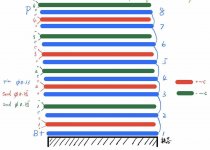
This is the coil arrangement I planed
View attachment 630269
View attachment 630270
8 layers of prim and 8 layers of second
Better if you do 9 primaries and 8 secondaries. The first and the last primaries will have 1/2 turns. That's symmetric. It's easy if the first and last primaries have, for example, 1 layer and those in the sandwich have 2 layers... or 2 and 4.....or 3 and 6 asnd so on....
Yours is not.....because it looks like the first primary has the same turns as one in the middle but is only coupled on one side. The last secondary has the same turns as one in the middle but is only coupled on one side.
It is not important that the ratio is precisely 5:1. If that worries you...
Last edited:
- Status
- This old topic is closed. If you want to reopen this topic, contact a moderator using the "Report Post" button.
- Home
- Amplifiers
- Tubes / Valves
- Audio Note M10 Clone

