I see many situations where a blind test is the only alternative
to find out what is a real sound difference and an imaginary illusion.
This is not unique for audio.
Blind tests is the only instrument to get knowledge
in many other areas.
Question is why many refuse to recognize this test method within audio.
When it is a valid way to investigate things,
and used to verify scientific works.
If you do not know your own mind, you do not know much,
because your mind is the filter of reality around you.
Because many vendors of snake oil in audio had been without work.lineup said:... Question is why many refuse to recognize this test method within audio ...
It's very suspect when any person rejects a DBT. For me, this is a signal which the person has something to hide.
lineup said:If you do not know your own mind, you do not know much,
because your mind is the filter of reality around you.
Lineup, if your mind is the filter of reality as you suggest, there then exists no reality but that which the filter in your mind says is reality, which "reality" can only therefore but reflect that filter, and nothing else. But what, then, is meant by "reality"?
I think it germane, when speaking to the issue of A/B testing, to ask just what level of subtlety that testing reasonably might be expected to identify. If important elements of an audio signal fall below that threshold, A/B testing is useless respecting those elements.
O.K. Here it is:
The two drivers are R1 and R2. The nonlinear resistance of the drivers is formed by the multipliers and voltage sources. The gain of the voltage sources is set such that the resistance nonlinearity is approx +-3% @ 1 Volt peak. As mentioned before I don't know what the actual nonlinearity with real drivers is (any hints or tips ?).
The drivers are crossed over with an LR2 @ 1 kHz. The nonlinearity of a real-life crossover is neglected but it can be assumed that it would only make matters worse.
Keep in mind that this model can only take the mutual influence on the electrical side into account. So I "generously" omitted the nonlinear transfer from voltage to sound pressure which can make matters worse or better. The same accounts for the acoustic summation of the signals.
The arrangement is fed with 1 Volt peak @ 500 Hz and the with 0.25 Volts (i.e. 12 dB less) @ 2kHz. Single- and bi- wiring can be changed by changeing the values of R3 to R4.
I will post the simulation results in subsequent posts.
Regards
Charles
Attachments
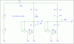
This is the simulation for the single-wire case
The interesting part is the signal levels at 500 Hz 1 kHz and 2 kHz:
Woofer Tweeter
500 Hz 1.255 V 317 mV
1 kHz 22.9 mV 2.08 mV
2 kHz 77.2 mV 312 mV
Sidenote: As one can see - the tweeter will generate harmonics of the woofer signal as well.
The interesting part is the signal levels at 500 Hz 1 kHz and 2 kHz:
Woofer Tweeter
500 Hz 1.255 V 317 mV
1 kHz 22.9 mV 2.08 mV
2 kHz 77.2 mV 312 mV
Sidenote: As one can see - the tweeter will generate harmonics of the woofer signal as well.
Attachments
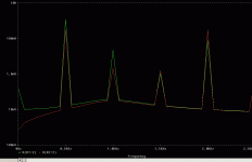
This is the simulation for the bi-wiring case. We now have two wires with 100 mOhms each - instead of once 50 mOhms.
Woofer Tweeter
500 Hz 1.24 V 320 mV
1 kHz 22 mV 1.5 mV
2 kHz 77.9 mV 309 mV
We can see a 25 % reduction of the 1 kHz content "accross the tweeter leads". Though any other voltage changes much less than that.
So there must be at least subtle differences between single-and bi- wiring that are more than just frequency-response irregularities. This mechanisms might also be another argument for AMPS with a (reasonably !) high DF.
Conclusion: If one doesn't use multi-billion-$ cables* this tweak might be a reasonable one to try out. Not for me though - I am a step ahead by running active.
Regards
Charles
* If you SELL said cables then this tweak is always reasonable.
Edit: Tried to make the tables with the values more legible but my changes don't have the same effect on the editor window than they do with the "real" view.
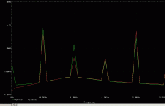
Attachments
Read the article, haven't read the 19 page thread, but i'll add my opinion:
Cables: I've actually worked with one particular 'high end' speaker cable that had zobel networks and other things built into a 'mystery box'... this was after one of my amplifier designs went unstable with it attached. I wouldn't go as far as to say all speaker cables sound the same, but I'll certainly say that you're safer buying lamp cord.
Tube amps and LP's: Tube amps have that distinct warm, even-order-harmonic sound. LPs can sound awful, especially when you're using a cheap turntable. For accurate audio reproduction, they're both terrible! But I grew up listening to my dad's LPs through a tube amp and I *love* that sound, despite the scratches and pops and harmonics and all that other stuff...
Burn-in lie: A properly designed piece of modern, digital/solid-state audio equipment won't burn in. But speakers age - spiders and surrounds get softer with more use, I've seen this first-hand in thiele-small measurements of speakers, and it can create big changes in sound. So full systems do "burn in", but I wouldn't finger the CD player or amplifier as the culprit...
Golden ear lie: Unfortunately, years of audio equipment design and DSP hardware/code work have left me with a trained ear for distortion. Golden ears do exist, and I'm ashamed to say I'm one of them.
To keep the math at a reasonably low level, I used DC for the confounding signal. That prevented the product of two sines, as the power at the cable R is (A + B)2 or (A2 + B2 plus 2 AB)....the voltage drop across the cable R then has a sqr(2AB) built in, hence the sidebands.phase_accurate said:This is the simulation for the single-wire case
The interesting part is the signal levels at 500 Hz 1 kHz and 2 kHz:
Woofer Tweeter
500 Hz 1.255 V 317 mV
1 kHz 22.9 mV 2.08 mV
2 kHz 77.2 mV 312 mV
Sidenote: As one can see - the tweeter will generate harmonics of the woofer signal as well.
Using the multipliers in the simulation introduces square (or 2 omega) components which blur the issue of harmonic distortion caused by the cable resistance itself. Would it be possible for you to run this simulation with pure load resistances, and at 4 amps lows/1 amp highs as I proposed?..After all, this mechanism works as current squared, I think higher power levels will cause more non linear grief...thank you in advance.
Or, an output impedance that can be set negative to zero the wires out? Or, pulling the feedback from a second set of speaker terminals, ones which tap in at the nodes of the crossover network.phase_accurate said:
Woofer Tweeter
500 Hz 1.24 V 320 mV
1 kHz 22 mV 1.5 mV
2 kHz 77.9 mV 309 mV
We can see a 25 % reduction of the 1 kHz content "accross the tweeter leads". Though any other voltage changes much less than that.
So there must be at least subtle differences between single-and bi- wiring that are more than just frequency-response irregularities. This mechanisms might also be another argument for AMPS with a (reasonably !) high DF.
By trying power levels consistent with reasonable listening, the non linearity may be far more important. If so, this analysis may require establishing a different set of guidelines for wire guage, based on the speaker's multiplicity, single, two way, three way, etc.phase_accurate said:
Conclusion: If one doesn't use multi-billion-$ cables* this tweak might be a reasonable one to try out. Not for me though - I am a step ahead by running active..
Thanks for the effort.
Cheers, John
phase_accurate said:Hi John
I will do it tomorrow.
Regards
Charles
I'll start a new thread to cull this analysis topic away from this one. Please post it there.
Thanks, John
AcidOrangeJuice said:
That if is a fact proven and verified is that DBT, when are done well....
It's true that to develop a DBT tests in hardware is more difficult, but nonimpossible. If your brother could not develop a hardware DBT test is because the circumstances did not allow it; but this is not a fault of the DBT test methodology. Another people, as for example Bob Carver, have been able to do this successful.
That's my point AOJ, the DBTs done by the AES which I've been able to find used very poor methodology. I anticipated the Stereophile link would be subjected to the criticism they lied to sell product so for independent confirmation I used the example presented by my brother. I don't understand how you arrived at the conclusion he structured DBT's for consumer audio or had met with failure. His background is in telephony and if you've ever used a Norstar or Venture you've heard some of his work. Nortel did not use engineers to structure DBT protocols, trained auditory specialists devised the methodology for engineers to implement. To reiterate, the opinion of an industry proffessional with years of structured DBT background witnessed first hand an AES demonstration intended to prove speaker cables make no difference and proclaimed it junk science. Before anyone makes the ad hominem objection he holds a biased view, my brother is not convinced passive devices make an audible difference and uses zip and generic interconnects. He's a cable agnostic.
To be extremely clear, because what people tell me I wrote is a fun-house reflection of what was on the page, I'm not saying DBTs have no value. What I am saying is the ones I've seen performed by the AES and others were extremely poorly structured and of no value. To my mind they were not structured to test a hypothesis but rigged to disprove a claim. If anyone can show be better examples I'm all eyes and ears.
gmarsh said:
Tube amps and LP's: Tube amps have that distinct warm, even-order-harmonic sound....
Hi gmarsh! I can get behind most of your post save this one. It's entirely possible to design a tube circuit with distortion well below any accepted scientific standard for audibility (which I know.) SY's line source posted in the tube forum for example. At best we can say tubes are an inefficient means towards that goal.
However it's possible I'm well behind the curve regrarding the latest auditory research. You and AOJ both mentioned direct experience in devising compression codecs, if you can point me to some recent research in the field I'ld be greatly appreciative!
SY said:FWIW, I totally agree- a mass "demonstration" is not the same thing as a proper valid sensory experiment. Did the presenters actually claim it to be such?
Hi daughter's baptism is in 20 minutes, I'll ask later.
daughter's baptism is in 20 minutes

Have you ever done a NERD test ? If so - how did you score ?
Regards
Charles
They tossed his score out, it was an outlier..really skewed the distribution..phase_accurate said:
Have you ever done a NERD test ? If so - how did you score ?
Regards
Charles
(I know...been there, done that.. )Geeze, at least he doesn't have a laptop wireless rig with silent keys...he coulda balanced the laptop on his daughter...
Whoa..
Cheers, John
A^2 + B^2 unequal (A+B)^2
I had a deeper look at John's posting regarding the missing 2AB.
I now see what is wrong with it. He makes the wrong assumption that the audio signal follows the sum of the acoustic powers and therefore at every point down the audio-chain we would have a scaled version of the sum of acoustic power again which can be split back into seperate powers by simple linear operations.
It is not that simple though:
The signal-voltage represents the sum of sound-PRESSURE levels.
There are the same relationships between sound-power and SPL as there are between electrical power and voltage. That means for the same circumstances power raises with the square of the RMS -voltage/-SPL !
So far so good.
What happens if we now add two sinusoids of different frequency ? Is the RMS voltage of the two added signals of RMS value A and B now A+B ??? No it isn't !!!! Since they sum UNCORRELATED their new RMS value is:
SQRT(A^2 + B^2)
Now check by yourself if you would still get a missing 2AB !
BTW: If John's observations were true they would indeed have nothing to do with cables as such but they would occur in every single little part of the whole chain !
Regards
Charles
Sorry Charles, but the mystery is there even if you replace the speakers with resistive loads and filters only. However, this assumption of filters, but not modelling them might have something to do with the mystery, although I am not so sure about that either.
Edit:
Maybe you are right, though, about the summation of sines of different frequencies. That i something I have been wondering about too. However, do note that John is interested in the instantaneous values, not the RMS values.
Edit:
Maybe you are right, though, about the summation of sines of different frequencies. That i something I have been wondering about too. However, do note that John is interested in the instantaneous values, not the RMS values.
- Status
- This old topic is closed. If you want to reopen this topic, contact a moderator using the "Report Post" button.
- Home
- General Interest
- Everything Else
- 'Audio Lies'