
Here are some tips on how to tweek this amp - I've done this and a few other things, but you will not get the simple dynaco phono stage to sound really great... If you have time and patience you can replace it with something slightly more exotic (like allen wright's) .
two main options:
a “basic” and an “extreme” one.
BASIC (costing about US $ 70 in passive components):
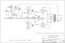
1. Replace the EL 34 cathode resistors with Resista type and remove the poor electrolytic capacitors connected in parallel to these resistors, whose function is to partially decouple them and, consequently, to “soften” clipping at high volume levels. The tweak will help reduce sound grain. Clipping will be sharper, but you won’t face the problem at all with sensitive speakers. If you don’t want to remove these capacitors, replace them with high grade audio types such as Elna Cerafine or Nichicon Muse. Just remove them
2. Remove the two input 0.22mF/400V ERO MKT 1813 capacitors. Their only function is to protect the circuit from possible residual AC (EU requirements?): signal will be cleaner.
3. The two generic 100mF/50V cathode electrolytic capacitors in the drive stage should be replaced with Elna Cerafine or Nichicon Muse types. You should extend the tweak to the phono stage, if you use it often. go for elna cerafine if you can find them
4. Decoupling capacitors: the generic 33mF/350V capacitors decoupling the drive and final stages should be replaced with compact radial or snap-in 105°C low ESR types. If you go for 450V then it will sound a bit dark at first - you can also use 47uf caps here...
5. Input selectors: they are quite poor and should be replaced with bettertypes (silver contacts), ensuring great precision for long periods if the ones you have are good then skip this
6. Volume control: the original potentiometer is of poor quality: a standard ALPS will guarantee a long life with no “scratches”. a good stepped attenuator also work wonders, but good luck fitting it in the small chassis...
EXTREME (add further US $ 120):
7. Power supply: replace the generic bridge rectifiers with IR Hexfred HFA08TA60C (anode voltage) and Schottky SB 340 soft recovery diodes (driving and phono stage filaments); The schotty sb340's make a big difference. the hexfred rectifier can be skipped
8. Coupling capacitors: the AI 500 is equipped with very good ERO MKT 1813 capacitors, among the best sounding in the polyester series. Yet, their replacement with Jensen paper in oil capacitors (aluminium foil) will allow a significant improvement in detail, depth and imaging. The considerable dimensions of paper in oil capacitors make replacement complicated, as it implies a new design in the printed circuit of the stage. Its hard to fit Jensens in the chassis - go for some russians - they're smaller, much cheaper and sound as nice or better
9. Replace Beyschlag metal film anodic resistors with 2W matching pairs Allen Bradley carbon film resistors. you can go for other brands of quality resister here, but AB's are cheap and do the trick. match them well though.
two main options:
a “basic” and an “extreme” one.
BASIC (costing about US $ 70 in passive components):
1. Replace the EL 34 cathode resistors with Resista type and remove the poor electrolytic capacitors connected in parallel to these resistors, whose function is to partially decouple them and, consequently, to “soften” clipping at high volume levels. The tweak will help reduce sound grain. Clipping will be sharper, but you won’t face the problem at all with sensitive speakers. If you don’t want to remove these capacitors, replace them with high grade audio types such as Elna Cerafine or Nichicon Muse. Just remove them
2. Remove the two input 0.22mF/400V ERO MKT 1813 capacitors. Their only function is to protect the circuit from possible residual AC (EU requirements?): signal will be cleaner.
3. The two generic 100mF/50V cathode electrolytic capacitors in the drive stage should be replaced with Elna Cerafine or Nichicon Muse types. You should extend the tweak to the phono stage, if you use it often. go for elna cerafine if you can find them
4. Decoupling capacitors: the generic 33mF/350V capacitors decoupling the drive and final stages should be replaced with compact radial or snap-in 105°C low ESR types. If you go for 450V then it will sound a bit dark at first - you can also use 47uf caps here...
5. Input selectors: they are quite poor and should be replaced with bettertypes (silver contacts), ensuring great precision for long periods if the ones you have are good then skip this
6. Volume control: the original potentiometer is of poor quality: a standard ALPS will guarantee a long life with no “scratches”.
a good stepped attenuator also work wonders, but good luck fitting it in the small chassis...EXTREME (add further US $ 120):
7. Power supply: replace the generic bridge rectifiers with IR Hexfred HFA08TA60C (anode voltage) and Schottky SB 340 soft recovery diodes (driving and phono stage filaments); The schotty sb340's make a big difference. the hexfred rectifier can be skipped
8. Coupling capacitors: the AI 500 is equipped with very good ERO MKT 1813 capacitors, among the best sounding in the polyester series. Yet, their replacement with Jensen paper in oil capacitors (aluminium foil) will allow a significant improvement in detail, depth and imaging. The considerable dimensions of paper in oil capacitors make replacement complicated, as it implies a new design in the printed circuit of the stage. Its hard to fit Jensens in the chassis - go for some russians - they're smaller, much cheaper and sound as nice or better
9. Replace Beyschlag metal film anodic resistors with 2W matching pairs Allen Bradley carbon film resistors. you can go for other brands of quality resister here, but AB's are cheap and do the trick. match them well though.
AI 800 output transformer
Do you know where I could get an output transformer for an Audio Innovations Series 800 MKiii? O r somewhere to get it rewound?
Thanks,
Jason Walker
chryslerjay@excite.com
Do you know where I could get an output transformer for an Audio Innovations Series 800 MKiii? O r somewhere to get it rewound?
Thanks,
Jason Walker
chryslerjay@excite.com
1. Replace the EL 34 cathode resistors with Resista type and remove the poor electrolytic capacitors connected in parallel to these resistors, whose function is to partially decouple them and, consequently, to “soften” clipping at high volume levels. The tweak will help reduce sound grain. Clipping will be sharper, but you won’t face the problem at all with sensitive speakers. If you don’t want to remove these capacitors, replace them with high grade audio types such as Elna Cerafine or Nichicon Muse. Just remove them
2. Remove the two input 0.22mF/400V ERO MKT 1813 capacitors. Their only function is to protect the circuit from possible residual AC (EU requirements?): signal will be cleaner.
3. The two generic 100mF/50V cathode electrolytic capacitors in the drive stage should be replaced with Elna Cerafine or Nichicon Muse types. You should extend the tweak to the phono stage, if you use it often. go for elna cerafine if you can find them
4. Decoupling capacitors: the generic 33mF/350V capacitors decoupling the drive and final stages should be replaced with compact radial or snap-in 105°C low ESR types. If you go for 450V then it will sound a bit dark at first - you can also use 47uf caps here...
EXTREME (add further US $ 120):
7. Power supply: replace the generic bridge rectifiers with IR Hexfred HFA08TA60C (anode voltage) and Schottky SB 340 soft recovery diodes (driving and phono stage filaments); The schotty sb340's make a big difference. the hexfred rectifier can be skipped
8. Coupling capacitors: the AI 500 is equipped with very good ERO MKT 1813 capacitors, among the best sounding in the polyester series. Yet, their replacement with Jensen paper in oil capacitors (aluminium foil) will allow a significant improvement in detail, depth and imaging. The considerable dimensions of paper in oil capacitors make replacement complicated, as it implies a new design in the printed circuit of the stage. Its hard to fit Jensens in the chassis - go for some russians - they're smaller, much cheaper and sound as nice or better
9. Replace Beyschlag metal film anodic resistors with 2W matching pairs Allen Bradley carbon film resistors. you can go for other brands of quality resister here, but AB's are cheap and do the trick. match them well though.
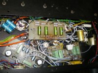
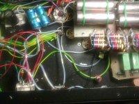
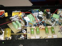
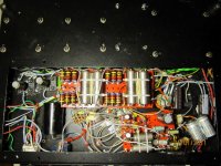
Hi,\\As I don't know much about all circuits, is it possible that you can post some photo's of each of the upgrades? That wil help me a lot!
Ad.
Attachments
Hello!
I read your recommendations on the amplifier Audio Innovations 500. Very interested! I have the same.
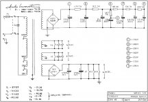
I want to ask you a question. In my amp the voltage at the reference points differ from those in the scheme:
C - 360v. (Instead of 390v) D - 354v. (Instead of 380v.) E - 322v. (350) F - 283v. (300) I - 214v. (235) R - 25v. (28)
DC - 5,9 v. (6,3) but AC-6,3 v - for tubes V4-V9 - correct. 'll Show why? I would be very grateful for the tip!
KOROVIN.
I read your recommendations on the amplifier Audio Innovations 500. Very interested! I have the same.
I want to ask you a question. In my amp the voltage at the reference points differ from those in the scheme:
C - 360v. (Instead of 390v) D - 354v. (Instead of 380v.) E - 322v. (350) F - 283v. (300) I - 214v. (235) R - 25v. (28)
DC - 5,9 v. (6,3) but AC-6,3 v - for tubes V4-V9 - correct. 'll Show why? I would be very grateful for the tip!
KOROVIN.
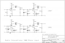
I rebuild the AI500 and placed new paper in oil capacitors and Allen Bradley resistors
that's working super.
I also want to remove the phono stage
Can somebody help with tips for that
Ad.
Hi.Please tell us what brand 33mF/350V capacitors?
KOROVIN.
Hi.Please tell us what brand 33mF/350V capacitors?
KOROVIN.
There are Russian NOS type.
Ad.
the upgrade ent further ander further.
I got rit of the phono part in the Ai 500 and changed tube settings.
Also I switched the potmeter to another place. I have more room for a shunt attenuator which I shortly want to make.
hereby a pic of the latest AI lay-out.
I got rit of the phono part in the Ai 500 and changed tube settings.
Also I switched the potmeter to another place. I have more room for a shunt attenuator which I shortly want to make.
hereby a pic of the latest AI lay-out.
Attachments
Hi, I am restoring an Audio Innovations series 500 integrated amp, the one with EL34. My problem is connecting the power transformer primary wires. From the PSU diagram from drtube:
http://www.drtube.com/schematics/ai/ai500-89-4.gif
the color wires are not shown, my amp has 8 (I think) wires: blue and brown on switch, and red, yellow,purple, black, orange and grey. Does anyone know how to connect the jumpers? Actually I need 120V. Thanks, Frederic.
http://www.drtube.com/schematics/ai/ai500-89-4.gif
the color wires are not shown, my amp has 8 (I think) wires: blue and brown on switch, and red, yellow,purple, black, orange and grey. Does anyone know how to connect the jumpers? Actually I need 120V. Thanks, Frederic.
- Home
- Amplifiers
- Tubes / Valves
- Audio Innovations Series 500 problems