I am absolutely blown away by your build. Happy Ian is taking a break and letting his creativity flow. Looking forward to seeing the fruits of his labor and what is next. I hope to see your final build pictures one day, truly inspiring and must sound amazing!
Thank you WuBai for your kind words! That means a lot, I will certainly take some time to come back and post on the finished build.
Serious setup Sebby. Nice work.
Here is mine of late.
StationPi, 5v Pi power from Salas L adaptor. 3v3 clean to fifo from Salas Reflektor D. Ian Receiver in there too. 3v3 dirty by Salas Ubib.
Another Ubib powering Abraxalito Phideca dac. Ian 6v6 Lipomini powering Andrea Mori clock TWTMC PPG. Currently trying this dac over the Ian dual ESS . I'll try the Miro AD1862 in here too sometime
Awesome work Jim! Good to see so many Salas products in there. I was going through the list of what you have in there and couldn't work out how you fit it all in.
I'd love to hear your thoughts on the Phideca. I do feel the ESS needs a lot of work to get sounding good - I think you have to avoid the modulator, get the output stage right and great power supplies to remove that ESS signature.

Hello, ESS 9038 cannot accept 48Fs, correct? But fifopi ultimate Q3 will change this to 64fs? The goal is CD-Pro i2s output to DAC. Thanks!FifoPi doesn't change the 48Fs into 64Fs. HdmiPi and TransportPi are also have no problem with 48Fs. The only thing is that you have to make sure your DAC works for 48Fs. (There will be no problem if your DAC was working with the I2S from your CD-Pro)
Design a small gear for DDDAC.
The U.FL input adapter
great creative idea Ian!
The reason is that the CD-Pro's SCK frequency can not be generated directly from 22/45 MHz MCLK. You can try a 16.9344/33.8688 MHz clock on FifoPi.Hello, ESS 9038 cannot accept 48Fs, correct? But fifopi ultimate Q3 will change this to 64fs? The goal is CD-Pro i2s output to DAC. Thanks!
Hi, can you do similar adapter for generic 2.54mm pinout [4x2] and four u.fl connectors MCLK/LRCK/BCLK/SDATA?
this is great idea to use u.fl connectors with 2.54mm pinout (without adapting cables)...
IS U.FL input adapter free? Is it possible to provide Gerber files?
Any thoughts on this with SinePi (and further down the road with a reference 10MHz clock on the input)?
FOS-3 OCXO
https://www.ebay.com/itm/283904223829
FOS-3 OCXO
https://www.ebay.com/itm/283904223829
OCXO phase noise is very low, but to convert 10M to music needs frequency will reduce performance, and also increase the cost, so it is not as good as using ndk oscillator.
Any thoughts on this with SinePi (and further down the road with a reference 10MHz clock on the input)?
FOS-3 OCXO
https://www.ebay.com/itm/283904223829
By increasing the cost you mean the (increased) quality of an external 10Mhz clock in order to compensate for the performance reduction of the multipliers?OCXO phase noise is very low, but to convert 10M to music needs frequency will reduce performance, and also increase the cost, so it is not as good as using ndk oscillator.
The following links have some EVALUATION KITS that can lock the OCXO to generate the required Clock, but refer to the Phase noise in the datasheet, maybe you can compare it with the NDK data to see if the value is worth the cost.
https://www.skyworksinc.com/en/Products/Timing/Evaluation-Kits#collapseGeneral
https://www.skyworksinc.com/en/Products/Timing/Evaluation-Kits#collapseGeneral
This continuous reference that you make to NDK is not constructive. I have looked in the datasheets that you have referenced (kind of - if we think about the fact that you are pointing to a bunch of products and most of them do not contain any datasheet; only user manuals and circuit schematics). I am not here to promote a certain product or another, however I have the feeling that some people are here just for that. I was just asking for opinions and maybe experience with this product and if the addition of a Rubidium high quality in front of it would have the capability of producing good results. You could have simply answered for instance: "usually this this kind of product would introduce a phase noise y that would negate any benefit of using Rubidium clock"The following links have some EVALUATION KITS that can lock the OCXO to generate the required Clock, but refer to the Phase noise in the datasheet, maybe you can compare it with the NDK data to see if the value is worth the cost.
https://www.skyworksinc.com/en/Products/Timing/Evaluation-Kits#collapseGeneral
Hi to all,
i try to post my problem also here hoping someone can help me
I made a mistake using my LifePO4 mkII: i inverted the polarity of the battery in the BT6 position (I saw some sparks but nothing more).
Now when I turn on the system i have the correct voltage on J1 and J2 (i'm using the system with 4 battery but i'm using only J1 and J2)
BUT
when I turn off the system and it goes in "charging" mode, the BT6 doesn't charge the battery.
All other 3 batteries are charged properly.
the problem is that if battery BT6 is below the threshold, the system charges the other batteries continuously without interrupting (and therefore overcharges them).
If I remove the battery BT6 (to try to use the system only with the other 3 battery, BT7, BT5 and BT2) the voltage meter on the board measures around 2V, and so again try to overcharge the battery.
I suppose I burned something but I don't know what.
Can you suggest me something to control or to change on the board ?
There is another way to avoid using the BT6 battery ?
Alternatevely I have a crazy idea
Considering i'm using only two output on the lifepo4 (j1 and j2), to avoid the recharging problem may i put the battery in BT5 position connected in parallel with the BT6?
In this way when the system is ON on j1 i have two battery connected in parallel.
During the recharge phase both battery are recharged via BT5
I don't have the electric schema of the board and so i'm not sure to make a good thing or i will destroy everything
Hoping someone can answer me i salute you
Thanks to Ian that suggested me to check some protector resistors behind the board. It seems I have two resistors burned. I've already ordered and I'm waiting for them.Hi to all,
i try to post my problem also here hoping someone can help me
I made a mistake using my LifePO4 mkII: i inverted the polarity of the battery in the BT6 position (I saw some sparks but nothing more).
Now when I turn on the system i have the correct voltage on J1 and J2 (i'm using the system with 4 battery but i'm using only J1 and J2)
BUT
when I turn off the system and it goes in "charging" mode, the BT6 doesn't charge the battery.
All other 3 batteries are charged properly.
the problem is that if battery BT6 is below the threshold, the system charges the other batteries continuously without interrupting (and therefore overcharges them).
If I remove the battery BT6 (to try to use the system only with the other 3 battery, BT7, BT5 and BT2) the voltage meter on the board measures around 2V, and so again try to overcharge the battery.
I suppose I burned something but I don't know what.
Can you suggest me something to control or to change on the board ?
There is another way to avoid using the BT6 battery ?
Alternatevely I have a crazy idea
Considering i'm using only two output on the lifepo4 (j1 and j2), to avoid the recharging problem may i put the battery in BT5 position connected in parallel with the BT6?
In this way when the system is ON on j1 i have two battery connected in parallel.
During the recharge phase both battery are recharged via BT5
I don't have the electric schema of the board and so i'm not sure to make a good thing or i will destroy everything
Hoping someone can answer me i salute you
I hope this will solve my problems and I don't have nothing else broken.
I also checked in the board manual and effectively there is a section that describe how to solve the problem.
Thanks again Ian
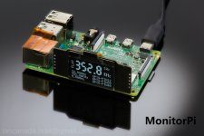
MonitorPi
I finally made it to integrate a real time I2S/DSD signal analyzer into a tiny ARM chip.
MonitorPi is a universal digital audio signal analyzer & OLED display. It can be applied to any RPi audio application and/or any other audio application. Even just on top of GPIO of a RPi only.
MonitorPi is capable of analyzing/displaying signal up to PCM768 KHz and DSD1024. No software/driver is needed. The OLED screen is 1.3”. I’m trying to use a big font to make it clearly seen in the distance.
It's a really interesting gear. By using it we can have a nice display for any project. And debugging a system will be also no longer an issue.
Ian
Attachments

That would be a very addition indeed!MonitorPi
I finally made it to integrate a real time I2S/DSD signal analyzer into a tiny ARM chip.
MonitorPi is a universal digital audio signal analyzer & OLED display. It can be applied to any RPi audio application and/or any other audio application. Even just on top of GPIO of a RPi only.
MonitorPi is capable of analyzing/displaying signal up to PCM768 KHz and DSD1024. No software/driver is needed. The OLED screen is 1.3”. I’m trying to use a big font to make it clearly seen in the distance.
It's a really interesting gear. By using it we can have a nice display for any project. And debugging a system will be also no longer an issue.
Ian
Hello,It is Ian's call of course, but my 2 cents: Ian spends Time, Buys parts, pays the SMD assembly company. So why would this be for free? Unless he wants to be....
")
I didnt touch my digital gear for a few weeks after not being able to make it work properly.
One of the things that could be the culprit is the u.fl connection between the circuit from Ian and the dddac motherboard so i should buy the adaptor and 3 new 6 inch cables.
Where to get the adaptor? Would be nice if it would be a available at Audio Creative or Audiophonics.
Greetings,Eduard
- Home
- Source & Line
- Digital Line Level
- Asynchronous I2S FIFO project, an ultimate weapon to fight the jitter