We should open mind and tolerance with different ideas")
That project makes me thinking of a question:
We all know normally a PLL has poor phase noise performance comparing with crystal oscillators. However, does a PLL with a low close-in phase noise reference clock input still keep the low close-in phase noise at output? And what's the real benefit of an OCXO as PLL reference clock?
Ian
I'm totally fine with 'new ideas' but these ideas arent new. they are just bad ideas, spending time, money and effort in an area that cannot present an improvement, even if the execution was good, which it isnt. not only is the initial premise to replace these non-audio clocks with something low jitter without any real reasoning, the execution is lacking and as you mention, they are driving a PLL and its just the standard PLL on the rpi.
I dont know that we should be tolerant of such charlatans. there do not appear to be any specs, or measurements. If anything I think we are too tolerant of this sort of nonsense already. in any normal industry, such companies would be taken to court for false advertising.
I dont know that we should be tolerant of such charlatans. there do not appear to be any specs, or measurements. If anything I think we are too tolerant of this sort of nonsense already. in any normal industry, such companies would be taken to court for false advertising.
In the old fashion designs, it was a VCO with a first order RC filter in front driven by the phase comparitor. Since it was a VCO, that opened all kinds of opportunity for extraneous effects; noise coupling, power supply, etc. Regardless of how slow the filter was designed.
I've no idea what a modern on-chip design is composed of. Maybe the same basic combo; phase comparitor, filter and VCO.
I only respond because I wondered the same thing recently. If I replaced a 12 MHz xtal with an oscillator board sporting low phase noise - knowing that this simply drove a chip internal PLL based frequency multiplier - would it help? Possibly only to a point, depending on other factors, some of which (besides a good power supply) would be out of my control.
We should open mind and tolerance with different ideas
That project makes me thinking of a question:
We all know normally a PLL has poor phase noise performance comparing with crystal oscillators. However, does a PLL with a low close-in phase noise reference clock input still keep the low close-in phase noise at output? And what's the real benefit of an OCXO as PLL reference clock?
Ian
Hey Ian, I for one would be very interested to see some testing on this. There are many audiophiles who are insistent on the benefits of better clocking for CPU/Networking etc. I haven't had a chance to compare in a controlled environment, so I haven't formed a subjective or objective opinion. Although I have tried retail devices with that claim and they sounded excellent.
I would be happy to lend you my 25.0 mhz Andrea SC-cut crystal (and board) to test, that I bought to test myself on a mobo/cpu but got distracted with work/life etc.
I'm totally fine with 'new ideas' but these ideas arent new. they are just bad ideas, spending time, money and effort in an area that cannot present an improvement, even if the execution was good, which it isnt. not only is the initial premise to replace these non-audio clocks with something low jitter without any real reasoning, the execution is lacking and as you mention, they are driving a PLL and its just the standard PLL on the rpi.
I dont know that we should be tolerant of such charlatans. there do not appear to be any specs, or measurements. If anything I think we are too tolerant of this sort of nonsense already. in any normal industry, such companies would be taken to court for false advertising.
Charlatans... Court for false advertising.. Someones having a bad day lol.
Last edited:
No need to make guesses. The clock arrangement of RPi I2S has been discussed here many times. One of the best posts is Henrik's https://www.diyaudio.com/forums/vendor-s-bazaar/355137-symphonic-mpd-24.html#post6250795
RPi4, I2S master (i.e. clocked internally), list of clocks:
The the configuration DTS files of the PCM (I2S) peripheral assign clock 54MHz osc -> PLL_D (3,000,000,091Hz) -> divider PLLD_PER (div by 4 i.e. 750,000,023Hz) -> MASH divider to PCM 3,071,997Hz average frequency (I2S 32bit slot => 3071997/64 = 47,999.95 Hz).
Clearly 3000000091/4/(48000*64) = 244.141 division ratio from PLL_D to the I2S bitclock. That's where the MASH kicks in (page 80 of https://datasheets.raspberrypi.org/bcm2711/bcm2711-peripherals.pdf ). In my case
ctl -> MASH 1, source PLL_D
DIVI: 0x0f4= 244
DIVF: 0x241 = 577
3,000,000,091/4/(244 + 577/4,096) = 3,071,997.02Hz
Clearly the division produces something close to the correct bitclock.
But the MASH does the fractional division by changing the divider 244 to 245 (for MASH 1) in some iterations. IMO it's simply 577-times dividing by 245 and 4096-577=3519-times dividing by 244. So the frequency flips between 3,073,770.58 and 3,061,224.582, which makes a difference in period 1.3ns.
Let me quote Ian's earlier measurements:
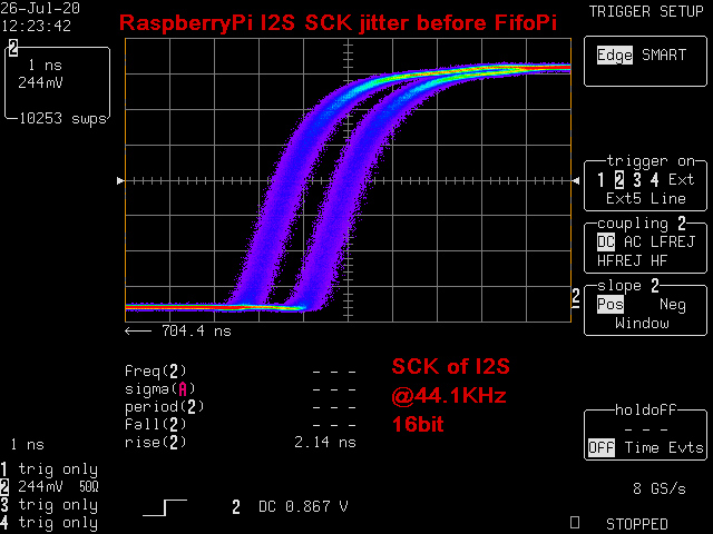
Or other measurements Comparing the I2S Capabilities of the RPi and Odroid C1+ | Himmelbauer IT Blog . The twice as long difference (2.6ns) is most likely caused by using older RPi with probably slower PLL_X clocks, making the limpy division more coarse.

Now tell me what impact does a different "osc" clock on jitter of the "pcm" clock generated by this limpy arrangement. Not even talking about the chances of being able to hear the change
RPi4, I2S master (i.e. clocked internally), list of clocks:
Code:
cat /sys/kernel/debug/clk/clk_summary
                                 enable  prepare  protect                                duty  hardware
   clock                          count    count    count        rate   accuracy phase  cycle    enable
-------------------------------------------------------------------------------------------------------
 ...............
 osc                                  4        4        1    54000000          0     0  50000         Y
    tsens                             0        0        0     3375000          0     0  50000         Y
    otp                               0        0        0    13500000          0     0  50000         Y
    timer                             0        0        0     1000000          0     0  50000         Y
    plld                              5        5        0  3000000091          0     0  50000         Y
       plld_dsi1                      1        1        0    11718751          0     0  50000         Y
       plld_dsi0                      1        1        0    11718751          0     0  50000         Y
       plld_per                       4        4        0   750000023          0     0  50000         Y
          pcm                         1        1        0     3071997          0     0  50000         Y
          emmc2                       1        1        0   100000003          0     0  50000         Y
          emmc                        0        0        0   250000007          0     0  50000         Y
          uart                        1        1        0    48000001          0     0  50000         Y
       plld_core                      1        1        0   600000019          0     0  50000         Y
    pllc                              3        3        1  2999999988          0     0  50000         Y
       pllc_per                       1        1        0   599999998          0     0  50000         Y
       pllc_core2                     0        0        0    11718750          0     0  50000         Y
       pllc_core1                     0        0        0    11718750          0     0  50000         Y
       pllc_core0                     2        2        1   999999996          0     0  50000         Y
          vpu                         3        3        1   500000000          0     0  50000         Y
             fe804000.i2c_div         1        1        1      100000          0     0  50000         Y
             aux_spi2                 0        0        0   500000000          0     0  50000         N
             aux_spi1                 0        0        0   500000000          0     0  50000         N
             aux_uart                 0        0        0   500000000          0     0  50000         N
             peri_image               0        0        0   500000000          0     0  50000         Y
    pllb                              2        2        0  1200000005          0     0  50000         Y
       pllb_arm                       1        1        0   600000003          0     0  50000         Y
    plla                              2        2        0  2999999988          0     0  50000         Y
       plla_ccp2                      0        0        0    11718750          0     0  50000         Y
       plla_dsi0                      0        0        0    11718750          0     0  50000         Y
       plla_core                      1        1        0   499999998          0     0  50000         Y
          h264                        0        0        0   499999998          0     0  50000         Y
          isp                         0        0        0   499999998          0     0  50000         Y
The the configuration DTS files of the PCM (I2S) peripheral assign clock 54MHz osc -> PLL_D (3,000,000,091Hz) -> divider PLLD_PER (div by 4 i.e. 750,000,023Hz) -> MASH divider to PCM 3,071,997Hz average frequency (I2S 32bit slot => 3071997/64 = 47,999.95 Hz).
Clearly 3000000091/4/(48000*64) = 244.141 division ratio from PLL_D to the I2S bitclock. That's where the MASH kicks in (page 80 of https://datasheets.raspberrypi.org/bcm2711/bcm2711-peripherals.pdf ). In my case
Code:
cat /sys/kernel/debug/clk/pcm/regdump
ctl = 0x00000296
div = 0x000f4241
ctl -> MASH 1, source PLL_D
DIVI: 0x0f4= 244
DIVF: 0x241 = 577
3,000,000,091/4/(244 + 577/4,096) = 3,071,997.02Hz
Clearly the division produces something close to the correct bitclock.
But the MASH does the fractional division by changing the divider 244 to 245 (for MASH 1) in some iterations. IMO it's simply 577-times dividing by 245 and 4096-577=3519-times dividing by 244. So the frequency flips between 3,073,770.58 and 3,061,224.582, which makes a difference in period 1.3ns.
Let me quote Ian's earlier measurements:
Or other measurements Comparing the I2S Capabilities of the RPi and Odroid C1+ | Himmelbauer IT Blog . The twice as long difference (2.6ns) is most likely caused by using older RPi with probably slower PLL_X clocks, making the limpy division more coarse.
Now tell me what impact does a different "osc" clock on jitter of the "pcm" clock generated by this limpy arrangement. Not even talking about the chances of being able to hear the change
Thanks Phofman, some really interesting insight. I will take some time to digest a lot of new information for me
However, I am referring to the "audiophiles" who have belief that improving the clocks for the actual SOC's on the device itself has subjective improvements. I cannot see how, but there are many who seem to think so.
Do you have the clocking configuration for the:
BCM2711B0
BCM54210
VLI VL805
Are they using a MASH divider?
As you said the clock performance of the GPIO is well understood and there are a variety of re-clocking boards to purchase.
Last edited:
Another topic I would be interested in hearing your thoughts. Your I2StoPCM board. It strikes me we go to great lengths with FIFO/ReclockPi/and SOTA clock to eliminate jitter, then the clean signal goes into I2StoPCM to be reconfigured into a synchronous PCM. Don't we introduce jitter in that process?That's really makes sense! Thanks.
However, I am referring to the "audiophiles" who have belief that improving the clocks for the actual SOC's on the device itself has subjective improvements. I cannot see how, but there are many who seem to think so.
There are people who believe the earth is flat. Or they belive that there was nobody on the moon. Does anyone seriously investigate the technical issues behind that?
Do you have the clocking configuration for the:
BCM2711B0
BCM54210
VLI VL805
IMO you might want to learn a bit about RPi4. BCM2711B0 is the SoC, its clocking arrangement was listed above. BCM54210 is the ethernet transciever, nothing to do the I2S clocking. It has a dedicated crystal. VL805 is the PCI-e USB3 controller, again has a dedicated crystal, again nothing to do with the I2S peripheral.
That replacement-crystals board is an absolute scam for affluent clueless audiophiles.
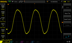
If the fractional part were always set to zero, the output frequency would slightly deviate from the requested value, but only clean integer divison would be used and no jitter from the MASH. A trivial patch
The resultant frequency differs from the requested one because the fractional part is missing. The code could be improved with rounding instead of flooring the int part.
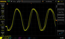
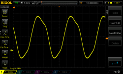
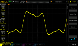
My scope is only 100MHz, at max. resolution 5ns/div the 1.3ns is hard to catch at slower rates. Therefore I started from higher frequencies. Scope traces in the same order.
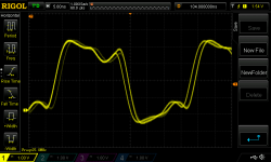
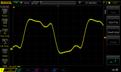
768000Hz vs. 781250Hz diff 1.8%
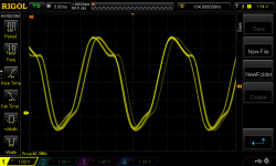
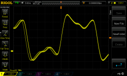
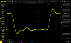
705600Hz vs. 732421Hz diff 4%
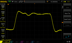
384000Hz vs. 390625Hz diff 1.7%
352800Hz vs. 355113Hz diff 0.7%
192000Hz vs. 192110Hz diff 0.06%
96000Hz vs. 96055Hz diff 0.06%
No scope traces:
88200Hz vs. 88778Hz diff 0.7%
48000Hz vs. 48027Hz diff 0.06%
44100Hz vs. 44221Hz diff 0.3%
If someone is willing to accept the playback speed error, the above patch vastly improves the jitter of I2S master on RPi.
Code:
diff --git a/drivers/clk/bcm/clk-bcm2835.c b/drivers/clk/bcm/clk-bcm2835.c
index 39fabced602a..e0dd36137135 100644
--- a/drivers/clk/bcm/clk-bcm2835.c
+++ b/drivers/clk/bcm/clk-bcm2835.c
@@ -1134,6 +1134,11 @@ static int bcm2835_clock_set_rate_and_parent(struct clk_hw *hw,
                ctl |= parent << CM_SRC_SHIFT;
        }

+       if (data->div_reg == CM_PCMDIV) {
+         // PCM clock, clearing fractional divider
+         div &= ~CM_DIV_FRAC_MASK;
+       }
+
        ctl &= ~CM_FRAC;
        ctl |= (div & CM_DIV_FRAC_MASK) ? CM_FRAC : 0;
        cprman_write(cprman, data->ctl_reg, ctl);
The resultant frequency differs from the requested one because the fractional part is missing. The code could be improved with rounding instead of flooring the int part.
My scope is only 100MHz, at max. resolution 5ns/div the 1.3ns is hard to catch at slower rates. Therefore I started from higher frequencies. Scope traces in the same order.
768000Hz vs. 781250Hz diff 1.8%
705600Hz vs. 732421Hz diff 4%
384000Hz vs. 390625Hz diff 1.7%
352800Hz vs. 355113Hz diff 0.7%
192000Hz vs. 192110Hz diff 0.06%
96000Hz vs. 96055Hz diff 0.06%
No scope traces:
88200Hz vs. 88778Hz diff 0.7%
48000Hz vs. 48027Hz diff 0.06%
44100Hz vs. 44221Hz diff 0.3%
If someone is willing to accept the playback speed error, the above patch vastly improves the jitter of I2S master on RPi.
Attachments
-
 768000-fract.png53.9 KB · Views: 267
 -
 768000-int.png43.6 KB · Views: 266
 -
 705600-fract.png53 KB · Views: 258
 -
 705600-int.png44 KB · Views: 62
 -
 384000-fract.png44.8 KB · Views: 49
 -
 384000-int.png38.6 KB · Views: 50
 -
 352800-fract.png43.6 KB · Views: 57
 -
 352800-int.png37.8 KB · Views: 66
 -
 192000-fract.png39.4 KB · Views: 69
 -
 192000-int.png36.3 KB · Views: 70
Yes, that's indeed.
Same RPi I2S SCK after FifoPi and ReClockPi
By a 1GHz digital oscilloscope.
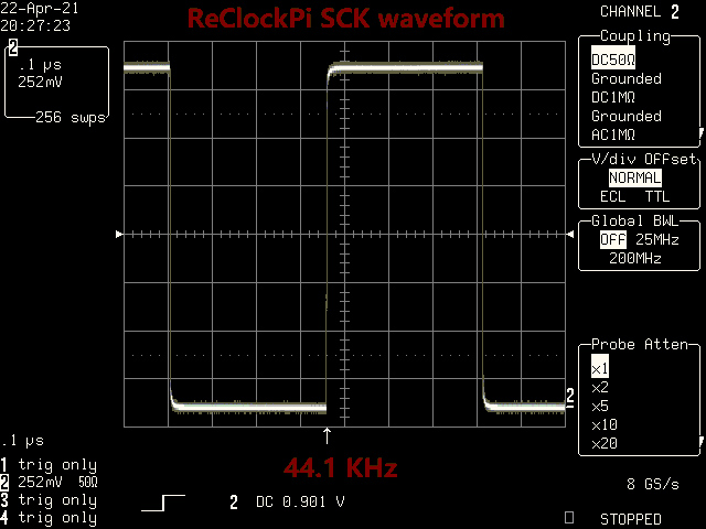
Sck44.1WaveformAfterReClockPi by Ian, on Flickr
Ian
Same RPi I2S SCK after FifoPi and ReClockPi
By a 1GHz digital oscilloscope.
Sck44.1WaveformAfterReClockPi by Ian, on Flickr
Ian
@sebbyp
we dont even know the supposed jitter performance of this clock and clock drivers, but even if its amazing sub picosecond jitter. what is the point of using that to clock a process that results in thousands of times more jitter? Utterly pointless.
Charlatanism, false advertising and in any regulated industry, criminal. It's a textbook example of all 3. Seems i'm not the only one who thinks so. I pulled punches and you still thought it was extreme. Thats a perfect example of the tolerance they don't deserve.
How would that go in your field of medical instrumentation Ian? not very well I imagine.
and no, not in a bad mood at all. My weekend just started
There are people who believe the earth is flat. Or they belive that there was nobody on the moon. Does anyone seriously investigate the technical issues behind that?
I don't understand, we are putting satellites in near orbit to create global internet (quite a big public fight going on about that right now) and humanity has been to space and taken images/videos to prove the earth isn't flat? The US is spending 9b to expand delivery capability to the moon right now. Let's not talk about China's big push on their space programme recently.. I think we can confirm serious investigation has been done and it's been proven since the ancient greeks. Pythagoras and Aristotle locked that in a while ago. I don't think anyone could seriously investigate, if they tried.
IMO you might want to learn a bit about RPi4. BCM2711B0 is the SoC, its clocking arrangement was listed above. BCM54210 is the ethernet transciever, nothing to do the I2S clocking. It has a dedicated crystal. VL805 is the PCI-e USB3 controller, again has a dedicated crystal, again nothing to do with the I2S peripheral.
That replacement-crystals board is an absolute scam for affluent clueless audiophiles.
Absolutely, I know next to nothing about the RPI4. However I understand what the SOC's do. The BCM5210 and VL805 reference a 25mhz clock? Isn't the purpose and claim of that board to replace/improve the clocking reference for those SOC's?
I'm not even sure how we could relate the 25mhz clock to the I2S output?
Anyway.
It's been interesting to see how telecoms engineers dealt with phase noise to manage millimetre waves in freq's above 6ghz, with the implementation of a Phase Tracking Reference Signal. Mainly to deal with the large phase noise in the PLL synthesisers due to the analog front-ends. They've managed to correct up to 1.5db in error vector magnitude and significantly increase transmission rate.
Obviously these are ultimately to manage challenging radio frequency performance at high freqs..However, I have been wondering is that what people are hearing.
If we have a large amount of phase noise, due to a not so great clocking references for SOC's responsible for data transmission - such as the USB pipe or the Ethernet transcoding. Could that generate random phase error and frequency offset (resulting in more phase error).
Would lower phase noise improve transmission quality and does it even matter. I would be particularly interested in the SOC's which are utilising PCI-E 3.0 as that is a high bandwidth and high-speed bus. PCI-E, I guess would have the best possible opportunity for transmission performance, as it's only ever two steps away, at most, from the CPU. Feels like a brilliant opportunity to test those theories.
I'm also curious about the Spread-Spectrum clock for the ethernet SOC. For every 8bit byte that cross overs the VL805 in 10 bits.. There are signal transitions.. Would lower clock phase noise help with better data recovery, error detection and word alignment.
Maybe I am being slow and missing your point. I'm curious to understand who has done or is doing research to debunk what is most likely not true. If it does have an impact, it would be very interesting to understand why.
I2S was created in the 80's. PCI-E 3.0, USB 3.0 and Gb Ethernet are so very different and designed for different purposes.
Last edited:
@sebbyp
we dont even know the supposed jitter performance of this clock and clock drivers, but even if its amazing sub picosecond jitter. what is the point of using that to clock a process that results in thousands of times more jitter? Utterly pointless.
Charlatanism, false advertising and in any regulated industry, criminal. It's a textbook example of all 3. Seems i'm not the only one who thinks so. I pulled punches and you still thought it was extreme. Thats a perfect example of the tolerance they don't deserve.
How would that go in your field of medical instrumentation Ian? not very well I imagine.
and no, not in a bad mood at all. My weekend just started
Fair enough, that particular board does look rubbish for a variety of reasons. Then again it's not exactly expensive. If someone is silly enough to buy it, their loss. Would be a guessing game, to understand what performance they did or didn't gain.
Then again, it's not hurting anyone and I'm certainly not offended by some entrepreneurial chap/business trying to make something.
I won't be buying it, that's for sure.
Yes, that's indeed.
Same RPi I2S SCK after FifoPi and ReClockPi
It would be sad if the FIFO did not clean the horrible jitter from the fractional division
But it would be interesting to see pictures of the RPi bitclock pin in the integer-only mode on your gear, not on my entry level scope with long interconnects. I believe it would be nothing outrageous, my 2 cents the 1GHz scope would show no visible jitter either.@phofman
Yes, there was no any visible jitter in the waveform on my 1GHz LC584AXL screen. However the jitter measurement package still tells the RMS time jitter of the SCK (or BCK) after FifoPi and ReClockPi was 3.76 ps. There is no ideal jitter cleaner in the real world, but FifoPi and ReClockPi did a good job, the result is already much much better than the original SCK from a RPi output, which was at 1000ps level!

Sck88JitterAfterReClockPi by Ian, on Flickr
Ian
Yes, there was no any visible jitter in the waveform on my 1GHz LC584AXL screen. However the jitter measurement package still tells the RMS time jitter of the SCK (or BCK) after FifoPi and ReClockPi was 3.76 ps. There is no ideal jitter cleaner in the real world, but FifoPi and ReClockPi did a good job, the result is already much much better than the original SCK from a RPi output, which was at 1000ps level!
Sck88JitterAfterReClockPi by Ian, on Flickr
Ian
the result is already much much better than the original SCK from a RPi output, which was at 1000ps level!
As shown above the fractional output from RPi always contains two frequencies with periods of 1,300 ps difference, by design. Your FIFO output must be (and is) many orders better, also by design
- Home
- Source & Line
- Digital Line Level
- Asynchronous I2S FIFO project, an ultimate weapon to fight the jitter