Accu range?
Nice caps, but only get used where realy required (high frequecny) in real world due to cost, and where used is usually gig ranges of frequencies. it would be interesting to see how they perform and whether resconant peaks are larger dure to lesser losses.
To others the value of the smallest case size possible is that once the res peak of the cap graph of a cap has been reached, it then acts as an inductor and thus is of no use. I wil try and find some data I have (possibly from AVX) for the different case sizes with various routing techniques (numer of vias, different route lengths) and effective frequencies they work up to. 0201 with microvia in pad are best, 0402's with two standard vias (0.5mm pad 0.25mm hole) has double the inductance of an 0402 with via in pad.
no, the GX range in 0201 but I got some Accu F as well for a comp cap in 0402 for AD797 based buffer reference/reg for clock duties and for Owens 'the wire' power amp, again comp for the LME49830. basically I got a few different types to try, a larger 1uf 0603 and 0402 X7R as well.
as to Via in pad, I plan to get a quote on that before sending off the gerbers, but i'm pretty sure it'll be extra and whether its worth going that far on a first spin i'm not sure, depends on what they come back with.
we are going for performance here though, not profit so much, but as the main target for it is the NTD1, which is Class A. lowest noise is the main factor, so adding a combo common mode/differential filter on the output is not such a big deal for the outputZ, so there will be optional placement for a choke->R before the ferrite, depends on the final layout.
anyway we should continue this by email as its not really on topic here.
Last edited:
I do power supplies for high rel and X7R are acceptable and often better tan most, also for local decoupling X7R's are better than COG. Anything less than an X7R shouldn't be used unless you want small package high value reservoir capacitors scattered around digital designs and need the space.
The only exception to this is on oscillators it is worth having a very low value (and thus small case size 0603 at least) COG for ultimate decoupling.
X7R are the best decoulers going, you get the smallest case size for a given value (and that is critical) and when using different values you get less resonant peaks than you would do with other capacitors. COG are not the best cap for decoupling digital designs, and once you get above about 20MHz the caps are basicvly not a lot of use. The actual decoupling is on die capacitance first, power plane capacitance second, small decouplers near the pins with the lowest inductance possible 3rd (that means small size) then reservoir capacitors and finaly power supply.
I often use this tool on complex designs to calculate and optimise the power delivery system for high rel complex designs:
http://www.algozen.com/DS_CADSTAR_LT_PowerIntegrityAdvanced_ENG_2011_10_05.pdf
This is on designs that often have to work at -40/+85 DEG C, life critical applications, that are tested to the nth degree at all temp ranges.
Thanks Marce for sharing your experiences on HF power supply decoupling. It’s very important for PSU design of an oscillator which is totally a different story than analog circuit. At HF, FR4 is no longer a pure insulator, capacitor are no longer what it was, as well as air ...
") .
. I use Cadence for simulation. But it seems it more focus on PCB layout design. What software are you using for simulation? Is there any evaluation version?
Ian
I use Cadstar and Cadstar SIV, again high speed stuff and this for power delivery system:
CADSTAR Power Integrity Advance | PCB Design | Zuken.
The cap stuff was some military communication system I worked on that we had some noise issue on. As clocks are always one of the main causwes a couple of engineers spent a lot of time investigating decoupling the oscillators, the COG handle the high frequency stuff, then the X7Rs for general decoupling. COG only was to resonant, the peaks causing more issues than they solved. X7R on there own had some high frequency mush, so the combination of both dielectrics gave the best results, the lossy X7Rs tamed the peaks the COG handled the high frequency mush.
I spent a week last year in Germany learning about power supply integrity and decoupling, I will try and find notes that are available for public consumption and send them you.
Microvia in pad is expensive, but with that you can get closely coupled powerplane pairs so its a win win situation. Look FOR IPC-2226 Type iii 2<X>2 construction or better, if cost is no option you can build the classiest digital circuits with low noise, a PC type circuit on this sort of construction is so quiet it would even appease the most ardent auiophile.
http://www.ncabgroup.com/wp-content/uploads/2012/01/hdi_presentation_110913.pdf
I use Cadstar and Cadstar SIV, again high speed stuff and this for power delivery system:
CADSTAR Power Integrity Advance | PCB Design | Zuken.
The cap stuff was some military communication system I worked on that we had some noise issue on. As clocks are always one of the main causwes a couple of engineers spent a lot of time investigating decoupling the oscillators, the COG handle the high frequency stuff, then the X7Rs for general decoupling. COG only was to resonant, the peaks causing more issues than they solved. X7R on there own had some high frequency mush, so the combination of both dielectrics gave the best results, the lossy X7Rs tamed the peaks the COG handled the high frequency mush.
I spent a week last year in Germany learning about power supply integrity and decoupling, I will try and find notes that are available for public consumption and send them you.
Microvia in pad is expensive, but with that you can get closely coupled powerplane pairs so its a win win situation. Look FOR IPC-2226 Type iii 2<X>2 construction or better, if cost is no option you can build the classiest digital circuits with low noise, a PC type circuit on this sort of construction is so quiet it would even appease the most ardent auiophile.
http://www.ncabgroup.com/wp-content/uploads/2012/01/hdi_presentation_110913.pdf
Thanks marce, I'll try some C0Gs caps to see if there is any positive to audio clock. Any brand do you recommend?
The micirvia is amazing. It is possible include them in PCB design? or it needs some special processing?
Regards,
Ian
So just to break it all down so that it is really simple, for a simple guy like me.
The high frequency (100kHz+) noise showing in the measurements on page 9 of the TPS7A datasheet (link) are a result of ringing in the cap+trace impedance and aren't something we would be able to address meaningfully with changes to parts selection on Ian's regulator PCB. Improvements at high freq should be addressed by capacitance right at the load, with improvements possible from PCB layout and via arrangement. I have seen diagrams in a book (Henry Ott) that show inductance of 0805 decoupling capacitor pads+vias(+traces) with a variety of different via arrangements, the inductance can vary from ~3nH to 0.4nH based on different via arrangements around the capacitor pads. Presumably the same arrangements make some gains on smaller footprint capacitors also. Microvia link Marce (thanks for the lunch time reading mate ) posted must be the next step and also better for compact layouts and to get maximum gain from REALLY small caps.
Changing caps on the TPS7A regulator board will have minimal impact on the performance above some threshold freq, based on the design's trace + connector inductance between the TPS7A4700 and the Si570.
Chris
The high frequency (100kHz+) noise showing in the measurements on page 9 of the TPS7A datasheet (link) are a result of ringing in the cap+trace impedance and aren't something we would be able to address meaningfully with changes to parts selection on Ian's regulator PCB. Improvements at high freq should be addressed by capacitance right at the load, with improvements possible from PCB layout and via arrangement. I have seen diagrams in a book (Henry Ott) that show inductance of 0805 decoupling capacitor pads+vias(+traces) with a variety of different via arrangements, the inductance can vary from ~3nH to 0.4nH based on different via arrangements around the capacitor pads. Presumably the same arrangements make some gains on smaller footprint capacitors also. Microvia link Marce (thanks for the lunch time reading mate
) posted must be the next step and also better for compact layouts and to get maximum gain from REALLY small caps.Changing caps on the TPS7A regulator board will have minimal impact on the performance above some threshold freq, based on the design's trace + connector inductance between the TPS7A4700 and the Si570.
Chris
Last edited:
basically yes, there is no guarantee it would even be at 100khz on Ians PCB, its differential mode noise, so thats why i've got placement for a ferrite and resistor, no cap is going to meaningfully effect it (remember caps will only shift the noise, not delete it) and besides, if its the measurement I think you are talking about, the 'ringing' is at 0.1nV/Hz... this isnt really something you can do anything about without knowing exactly the result in your system.
it looks as if its trending upwards in frequency with higher load current too, it may be an artifact of their load/probe (unlikely but possible) so at higher current like on Ians board, it will probably be pushed further up and it will probably not be as narrow, as the conditions for that measurement has it at 50mA and with only 10uf output cap
it looks as if its trending upwards in frequency with higher load current too, it may be an artifact of their load/probe (unlikely but possible) so at higher current like on Ians board, it will probably be pushed further up and it will probably not be as narrow, as the conditions for that measurement has it at 50mA and with only 10uf output cap
Last edited:
Ian, what configuration of optional control signals output port (J13, pins 2 and 3 - FIFO board) if Dual XO board in dual speed mode (XO-s 45.1584 and 49.1520 MHz) ?
Thanks.
Vladimir
I read in DoubleSpeedMode manual :
"1. The FIFO board will work with the Dual XO Clock Board in double speed mode automatically without need any additional setting " .
I read in DoubleSpeedMode manual :
"1. The FIFO board will work with the Dual XO Clock Board in double speed mode automatically without need any additional setting " .
Correct answer, thanks nvduybom!
Ian, what configuration of optional control signals output port (J13, pins 2 and 3 - FIFO board) if Dual XO board in dual speed mode (XO-s 45.1584 and 49.1520 MHz) ?
Thanks.
Vladimir
J13 reserved for future application, has nothing to do with double speed mode
Ian
I think we've misunderstood vd-two's question guys, I didn't get it until just now, re-reading the FIFO manual.
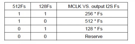
J13 is the output port to monitor *FS currently used, is this the same in 'normal' and 'double speed' modes? He isn't asking about setting the double speed mode, but how to use the J13 port to monitor while the FIFO is set for double speed, the current version of manual has missed this configuration by the looks.
The Page 6 of the FIFO manual shows this lookup table for J13 pin 2 and 3:
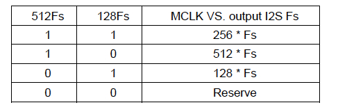
Is it fair to guess that 0, 0 might indicate 1024*Fs? This would be consistent with the LED status notifications so would make sense, I think.
Cheers,
Chris
J13 is the output port to monitor *FS currently used, is this the same in 'normal' and 'double speed' modes? He isn't asking about setting the double speed mode, but how to use the J13 port to monitor while the FIFO is set for double speed, the current version of manual has missed this configuration by the looks.
The Page 6 of the FIFO manual shows this lookup table for J13 pin 2 and 3:
Is it fair to guess that 0, 0 might indicate 1024*Fs? This would be consistent with the LED status notifications so would make sense, I think.
Cheers,
Chris
Attachments
Last edited:
I think Ian's busy getting GB orders filled so his usual speedy and detailed replies aren't possible while he has the higher workload, give him time
With the FIFO alone you'll have trouble working out the MCLK freq, I haven't seen an easy way to determine MCLK used on the DualXO board without having knowledge provided by the transport. I'd also be concerned about the speed at which you need to change the digital filters, the FIFO notification may come too late? If you tell us more about your source and project I could make some other suggestions while we wait for Ian to confirm my suspicion above (that both signals OFF = 1024*FS).
With the FIFO alone you'll have trouble working out the MCLK freq, I haven't seen an easy way to determine MCLK used on the DualXO board without having knowledge provided by the transport. I'd also be concerned about the speed at which you need to change the digital filters, the FIFO notification may come too late? If you tell us more about your source and project I could make some other suggestions while we wait for Ian to confirm my suspicion above (that both signals OFF = 1024*FS).
Hi Ian, hi Chris,
please add the needed current from each single module to the wiki page.
It would be a great help for those, who would like to use external shunt regulators e.g. Salas SSLV.
With the data we could set the correct shunt current value.
Thanks in advance,
Oliver

please add the needed current from each single module to the wiki page.
It would be a great help for those, who would like to use external shunt regulators e.g. Salas SSLV.
With the data we could set the correct shunt current value.
Thanks in advance,
Oliver
Hi Ian, hi Chris,
please add the needed current from each single module to the wiki page.
It would be a great help for those, who would like to use external shunt regulators e.g. Salas SSLV.
With the data we could set the correct shunt current value.
Thanks in advance,
Oliver
I measured the current for each moudle :
FIFO: 15mA
SPDIF:40mA
DualClock: 45-50mA
Cheer,
Van Duy
Hi Ian, hi Chris,
please add the needed current from each single module to the wiki page.
It would be a great help for those, who would like to use external shunt regulators e.g. Salas SSLV.
With the data we could set the correct shunt current value.
Thanks in advance,
Oliver
Hi Oliver,
I made two modifications to your (Salas) 5V shunt board. One was to lower the current limiting resistor to 3.9R (Kiwame) and the other was to add a 1N400X diode between the two LED's. The end result gives me ~6V and 500mA. This was the recommended power supply values Ian listed in the FIFO manual.
And...it sounds wonderful.
- Home
- Source & Line
- Digital Line Level
- Asynchronous I2S FIFO project, an ultimate weapon to fight the jitter