Demian,
the price of the OCXO is high, probably cheaper than a Wenzel-Croven but they ask 290 GBP for a custom part, excluding VAT and shipping. Maybe a group buy of at least 5 people could decrease the price, but don't expect great reduction, OCXO are anyway not cheap.
BTW, as I said in a previous post, I'm working on a cheaper alternative, using a high performance cold welded AT-cut crystal.
The prototype works on the breadboard, but I have to build a wired prototype (or better an air wired) to go to a university lab and test its phase noise (again, simple and quick with an Agilent phase noise measurement system and the professor who know how to use it).
I expect good results, but not the same of the OCXO. An AT-cut crystal does not reach the Q level of an SC-cut, but I believe a bit better than a Crystek or a Tentlabs But in this case also, the crystal only is more expensive than the previous finished XO.
If the results will be good as I expect, I'll develop the PCB and then I'll share all the information (schematic, PCB, measurements and so on).
Unfortunately I am not very productive, since my job leaves me just a little free time (congratulations to Ian who is really very efficient).
If anyone was interested, please be patience, a pair of months I hope.
warm up < 8 minutes, that means quick, also for those like me who have little time to spend on their hobbies.
Don't care about long term stability, since we are talking about audio application.
OK, it was an honest question, some OCXO take much longer to become stable to the point where they stop improving and then the PLL needs to become stable and the FFT takes time, not just after the element comes up to temp. still sounds like 30mins-1hr for a professional, who is being paid? may not be cheap, but again if they discount their time or are simply interested in the result, or you do not count time and the 20K diagnostics gear doesnt have to be paid for, then sure, all is easy, quick and free.
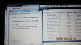
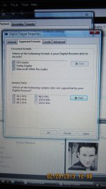
With Jriver 17 in Output mode is Drirect Sound or Wave out, my lossless system play normally but trouble with other Output mode, ex : Kernel Streaming, WASAPI output & WASAPI output-Event Style. Jriver 17 still playing but no sound and I see all the LEDs flashing in the DualXO clock board. Does anyone have this case ?. This error also appears when I use the Empirical Off-ramp 3.
Attachments
Last edited:
Ian,
I've updated wiki page to include GBIV docs. Most significant changes to the wiki are:
Si570, FIFO isol board, battery management and TPS7A4700 are no longer 'under development'
Links to the new docs provided for each of the above are now included in wiki.
Cheers,
Chris
I've updated wiki page to include GBIV docs. Most significant changes to the wiki are:
Si570, FIFO isol board, battery management and TPS7A4700 are no longer 'under development'
Links to the new docs provided for each of the above are now included in wiki.
Cheers,
Chris
Ian,
I've updated wiki page to include GBIV docs. Most significant changes to the wiki are:
Si570, FIFO isol board, battery management and TPS7A4700 are no longer 'under development'
Links to the new docs provided for each of the above are now included in wiki.
Cheers,
Chris
Hi Chris,
You did great job to the community. Others can save a lot of time from your summarized information. I'm highly appreciated. Thank you so much. Just hope everybody could realize that
") .
.Cheers,
Ian
With Jriver 17 in Output mode is Drirect Sound or Wave out, my lossless system play normally but trouble with other Output mode, ex : Kernel Streaming, WASAPI output & WASAPI output-Event Style. Jriver 17 still playing but no sound and I see all the LEDs flashing in the DualXO clock board. Does anyone have this case ?. This error also appears when I use the Empirical Off-ramp 3.
Do you have a oscilloscope? Can you find out what's wrong with the I2S signal?
In your normal playing, does dual xo clock board switching between 44.1K and 96K without problem?
Ian
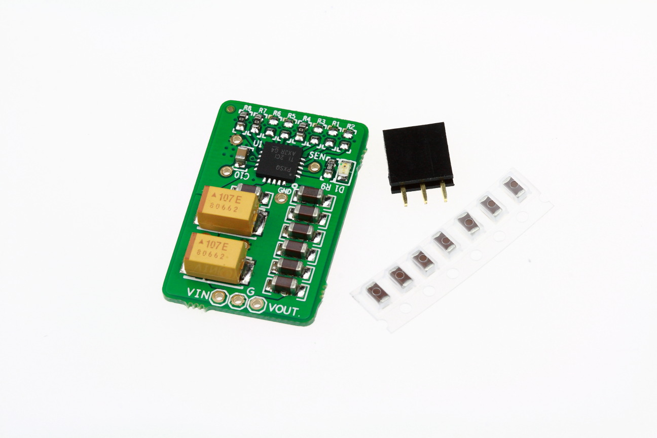
The pic Ian attached to the GBIV is probably the best one for it, there is a dot on the top corner of the TPS chip.
Note there are a few subtle changes to the layout of the board below, the chip orientation doesn't appear to be one of them though
At a glance the changes are something like: Extra output cap for 6 x10uF rather than 5x10uF; change of position for LED+resistor; Larger value input caps (now total of 200uF rather than 100uF total previously); there may be a few other tweaks Ian has done too, regardless, I don't think the prototype TPS7A regs had any inherent problems.
Last edited:
While we're talking about that TPS7A4700 reg.
I am wondering how much the X7R capacitor's non-linear capacitance wrt high frequencies impacts regulator performance, especially in the noise reduction LPF and the output. Is that HF noise mostly negated by local decoupling at the Si570? np0 caps are more linear wrt freq but aren't really available in the sizes we need on the output of this regulator. I'm also not keen on doing mix and match caps of different sizes to set up ringing and other dramas in the critical high freq area. I have tried looking for better alternative parts for the output caps or the CNR cap and other than different brand X7R or tant caps there isn't much around by the looks.
So from the above, I've come to the above that there isn't many places to gain a technical advantage from deviating from Ian's BOM. I guess that means Ian has thought through all of the above and come to the BOM selections for good reasons
I will probably do a few different versions with tant and panasonic spcap on the regulator input, just because I have a few boards to try.
Chris
Do you have a oscilloscope? Can you find out what's wrong with the I2S signal?
In your normal playing, does dual xo clock board switching between 44.1K and 96K without problem?
Ian
I resolved by setting the "Default format" in "Control Panel \ Sound" to the limit that my Amanero can get. Now, this error still occur when play files with format 24bit/192khz. I updated Amanero with the latest firmware and drivers.
Van Duy.
Attachments
Last edited:
While we're talking about that TPS7A4700 reg.
I am wondering how much the X7R capacitor's non-linear capacitance wrt high frequencies impacts regulator performance, especially in the noise reduction LPF and the output. Is that HF noise mostly negated by local decoupling at the Si570? np0 caps are more linear wrt freq but aren't really available in the sizes we need on the output of this regulator. I'm also not keen on doing mix and match caps of different sizes to set up ringing and other dramas in the critical high freq area. I have tried looking for better alternative parts for the output caps or the CNR cap and other than different brand X7R or tant caps there isn't much around by the looks.
So from the above, I've come to the above that there isn't many places to gain a technical advantage from deviating from Ian's BOM. I guess that means Ian has thought through all of the above and come to the BOM selections for good reasons
I will probably do a few different versions with tant and panasonic spcap on the regulator input, just because I have a few boards to try.
Chris
The MLCC capacitors are very interesting.
They have good high frequency performance comparing with tan and others. But the temperature characteristic are poor. You can do a test:
Measure the capacitance at room temperature by a capacitor mater. Then, use a hot gun heat the MLCC to around 100 degree C. Measure the capacitance again.
X7R +10% to 20%
X5R -10% to 20%
Y5V -50% to 70%
NP0 or C0G are best, but the capacitance too small.
MLCC from different brand sound slightly different. Similar to changing the audio interconnection cable
.Ian
remember the point of a regulator is to have a completely stable voltage at the output and particularly when powering clocks or references, I cant see the voltage coefficient would cause any problems on the output, as any voltage driven distortion is usually dynamic in nature.
on my TPS PCB i'm allowing for 0201 size for the noise reduction and output bypass on the underside (for low voltage/lowest noise application). I will be trying the thin film AVX caps here, they now go up to 10nf, but I will probably just stick to c0g with polystyrene film (relcap) option
my board is a bipolar reg, primarily for analogue, higher voltage applications
I guess my comment about HF capacitance was bought on after seeing this graph in wikipedia article on ceramic caps.
I haven't been able to find a similar graph in TDK/murata datasheets for their caps though so I've had some difficulty rationalising it. I would expect the HF performance to be also a function of the size of the capacitor so I was looking to see if a capacitor array may be used to improve HF performance of X7R for example. In the mean time I'll use X7R caps and keep hunting for other alternatives.
Chris
I do power supplies for high rel and X7R are acceptable and often better tan most, also for local decoupling X7R's are better than COG. Anything less than an X7R shouldn't be used unless you want small package high value reservoir capacitors scattered around digital designs and need the space.
The only exception to this is on oscillators it is worth having a very low value (and thus small case size 0603 at least) COG for ultimate decoupling.
X7R are the best decoulers going, you get the smallest case size for a given value (and that is critical) and when using different values you get less resonant peaks than you would do with other capacitors. COG are not the best cap for decoupling digital designs, and once you get above about 20MHz the caps are basicvly not a lot of use. The actual decoupling is on die capacitance first, power plane capacitance second, small decouplers near the pins with the lowest inductance possible 3rd (that means small size) then reservoir capacitors and finaly power supply.
I often use this tool on complex designs to calculate and optimise the power delivery system for high rel complex designs:
http://www.algozen.com/DS_CADSTAR_LT_PowerIntegrityAdvanced_ENG_2011_10_05.pdf
This is on designs that often have to work at -40/+85 DEG C, life critical applications, that are tested to the nth degree at all temp ranges.
Last edited:
yep, I got some x7r as well for the 1uf bypass at the input side (0402), but I really want to try out those silly expensive thin films =) as my only real wank value part on the board, I cant help myself . as well as providing space for the larger film (not a huge aerial, just 5mm) because for here low noise is preferable and I want to try a couple different things out.
other people will be getting the boards too, so I figure its good to leave a couple options to satisfy different peoples cap fetishes as long as it doesnt compromise the layout.
. as well as providing space for the larger film (not a huge aerial, just 5mm) because for here low noise is preferable and I want to try a couple different things out.other people will be getting the boards too, so I figure its good to leave a couple options to satisfy different peoples cap fetishes as long as it doesnt compromise the layout.
Last edited:
- Home
- Source & Line
- Digital Line Level
- Asynchronous I2S FIFO project, an ultimate weapon to fight the jitter