Hi AR2,
I think I can answer those for you
1. There is an API doc for the serial port in this post here.
2. The clock board is hard to use separately to the FIFO. I agree it would be nice but the only time that you can change the MCLK is when the input FS changes, within 100ms of 0xC1 event being sent from Ian's Si570. I am reading between the lines but I think this would be reliant on additional comms between the FIFO and Si570 to trigger this event in the Si570 local controller (on Ian's board). Since the FIFO protocols are not published (Ian was asked a few pages back and he has said he is reluctant at this stage to expose these internal workings of the FIFO) there is no way to trigger these events to allow the clock to change frequency separately to the FIFO eco-system. I think it may be possible to use the Si570 as a fixed speed MCLK for other systems at whatever MCLK rate was set previously and rely on async clocking.
I am writing separate control for Si570 already that will be available publicly when it is ready, but will not run on an Arduino. For hifiduino it would need glt to write some additional code for hifiduino to support Si570 comms to calculate the current Fs for output to your DAC LCD/VFD display when using synch mclk (which is what I think you're trying to achieve mainly right?).
Cheers,
Chris
Thanks Chris
")
Congratulations Ian!
Rally cool looking board. Just a few questions, that I might suspect answers:
1. I see Rxd and TxD contacts - what is the purpose of those? Is that for I2C that could be used with Hifiduino? Since right now Hifiduino does not display rate when used with FIFO, I hope new board will fix that. I think I recall earlier that conversation.
2. Is it possible to use new clock board stand a lone without FIFO? I am just curious since it will be good to have such variable clock board for experimentations. I see no reason why not, besides having something to select frequency, but I stand to be corrected.
Thank you
AR2
Hi AR2,
hochopeper gave correct answers, I just have a little bit addition to qusetion 2,
I think you want to use this Si570 board as a stand along digital audio clock generatior. The answer is YES.
This clock borad can be used as multi-frequency audio clock generator with 8 frequencies. You can use the on-board push button setting the frequency at any time. The set frequency will be saved into on-chip flash memory and will be recalled each time for next power up.
Regards,
Ian
Si570 Clock Board - Frequencies and xFs
Si570 clock board is designed to support digital audio stream from 44.1 KHz to 384 KHz, and xFs from 256*Fs to 2048*Fs. By taking the advantages of Si570, it could generate 8 audio frequencies, they are:
11.2896MHz, 12.2880MHz, 22.5792MHz, 24.5760MHz, 45.1584MHz, 49.1520 MHz, 90.3168 MHz, 98.3040MHz.
Among all of them, 90.3168 MHz and 98.3040MHz are optimized to ESS DACs.
Si570 clock board can work at both stand along mode and FIFO mode.
When working stand along as a universal digital audio clock generator without connecting to a FIFO, frequencies could be set manually at any time by the push button. The current setting will be stored into onboard flash memory and will be recall automatically after each power up.
When working together with a FIFO, frequencies and xFs will be switched automatically according to the input I2S Fs and the preset frequency and xFs combination group. Those combination groups could also be programmed by the on-board push button and will be saved into on-board flash memory. They are:
//Group1:Si570 frequency and *Fs combination for low mclk range
{F112896, 256*FS}, //2 44.1 KHz
{F122880, 256*FS}, //3 48 KHz
{F225792, 256*FS}, //4 88.2 KHz
{F245760, 256*FS}, //5 96 KHz
{F451584, 256*FS}, //6 176.4KHz
{F491520, 256*FS}, //7 192 KHz
{F903168, 256*FS}, //8 352.8KHz
{F983040, 256*FS} //9 384 KHz
// Group2:Si570 frequency and *Fs combination for low mid mclk range
{F225792, 512*FS}, //2 44.1 KHz
{F245760, 512*FS}, //3 48 KHz
{F225792, 256*FS}, //4 88.2 KHz
{F245760, 256*FS}, //5 96 KHz
{F451584, 256*FS}, //6 176.4KHz
{F491520, 256*FS}, //7 192 KHz
{F903168, 256*FS}, //8 352.8KHz
{F983040, 256*FS} //9 384 KHz
// Group3:Si570 frequency and *Fs combination for middle mclk range
{F451584, 1024*FS}, //2 44.1 KHz
{F491520, 1024*FS}, //3 48 KHz
{F451584, 512*FS }, //4 88.2 KHz
{F491520, 512*FS }, //5 96 KHz
{F451584, 256*FS }, //6 176.4KHz
{F491520, 256*FS }, //7 192 KHz
{F903168, 256*FS }, //8 352.8KHz
{F983040, 256*FS } //9 384 KHz
// Group4:Si570 frequency and *Fs combination for high mclk
{F903168, 2048*FS}, //2 44.1 KHz
{F983040, 2048*FS}, //3 48 KHz
{F903168, 1024*FS}, //4 88.2 KHz
{F983040, 1024*FS}, //5 96 KHz
{F903168, 512*FS }, //6 176.4KHz
{F983040, 512*FS }, //7 192 KHz
{F903168, 256*FS }, //8 352.8KHz
{F983040, 256*FS } //9 384 KHz
Group4 is highly recommended for ESS DACs and might be set as factory default.
An optional third party external controller could be used for display the clock board status and taking control of the frequency switching via UART port. But it's not a must.
Ian
Attachments
Ian, great news!
Maybe too late (the frequency groups were here for some time already) but I will try to kindly ask:
Would it be possible to add one more group (or modify the group1) also for older DAC chips like WM8741 or AK4396 that support master clocks up to 36Mhz (so 128fs is required)? This would support 176.4kHz and 192kHz sampling frequencies for those chips.
//Group0:Si570 frequency and *Fs combination for very low mclk range
{F112896, 256*FS}, //2 44.1 KHz
{F122880, 256*FS}, //3 48 KHz
{F225792, 256*FS}, //4 88.2 KHz
{F245760, 256*FS}, //5 96 KHz
{F225792, 128*FS}, //6 176.4KHz <---
{F245760, 128*FS}, //7 192 KHz <---
{F903168, 256*FS}, //8 352.8KHz
{F983040, 256*FS} //9 384 KHz
There is no LED for 128fs (I would have no problem with that) but it is probably too late to ask before GBIV. If it is so then I could get one double clock board for experiments with older chips.
Thank you.
Si570 doesn't talk i2c ... it needs a UART.
For DACs that require 128Fs I would suggest the DualXO board will give a better overall result. Remember that the Si570's main motivation was to enable the higher clock speeds for the ESS DACs the others are not the primary goal. There seems to have been a design decision by Ian to leave 128Fs out of the Si570.
Regarding 192 and 384Fs, these speeds haven't been supported by any of Ian's modules and I am only reading between the lines here but I believe that it may be related to the fact that they are not in the 2^x sequence (where x is an integer).
2^7 = 128
2^8 = 256
2^9 = 512
2^10 = 1024
...
Integer math is FAR quicker than floating point.
Last edited:
Could the si570 board be controled using I2C commands from, say, the Amanero board?
As a standalone device, It could be interesting having 192fs (AKM, AD, WM) or even 384fs for the PCM/DSD179x family.
Cheers
FIFO board supports only 128fs, 256fs and 512fs so they will be probably not supported by the si570 board. See Ian's answer in this post:
http://www.diyaudio.com/forums/digi...imate-weapon-fight-jitter-19.html#post3016396
as I understand it there is a lot more than changing clock speeds needed to mod amanero
I was thinking about the cheap Acko isolator relcoker plus the si570 as RFCK. Wouldn't this work?
Si570 doesn't talk i2c ... it needs a UART.
TBH I haven't read Ian's implementation but according to the SI570/571 datasheet (page 17) it would seem to support 2 wire I2C through pins 7 (SDA) and 8 (SDL).
This will work as long as you are wanting asynch re-clocking with Acko's board. See below.I was thinking about the cheap Acko isolator relcoker plus the si570 as RFCK. Wouldn't this work?
Yes the Si570 chip itself has an i2c interface. Ian has an on board controller that communicates with the Si570 and it is this controller that provides a UART API for external control of the board. This ensures that the external controller gets FIFO events (change of input freq) that would not be possible if he only provided the i2c port.TBH I haven't read Ian's implementation but according to the SI570/571 datasheet (page 17) it would seem to support 2 wire I2C through pins 7 (SDA) and 8 (SDL).
In your application I think setting a fixed freq and using asynch reclocking would be the best bet.
Ian, great news!
Maybe too late (the frequency groups were here for some time already) but I will try to kindly ask:
Would it be possible to add one more group (or modify the group1) also for older DAC chips like WM8741 or AK4396 that support master clocks up to 36Mhz (so 128fs is required)? This would support 176.4kHz and 192kHz sampling frequencies for those chips.
//Group0:Si570 frequency and *Fs combination for very low mclk range
{F112896, 256*FS}, //2 44.1 KHz
{F122880, 256*FS}, //3 48 KHz
{F225792, 256*FS}, //4 88.2 KHz
{F245760, 256*FS}, //5 96 KHz
{F225792, 128*FS}, //6 176.4KHz <---
{F245760, 128*FS}, //7 192 KHz <---
{F903168, 256*FS}, //8 352.8KHz
{F983040, 256*FS} //9 384 KHz
There is no LED for 128fs (I would have no problem with that) but it is probably too late to ask before GBIV. If it is so then I could get one double clock board for experiments with older chips.
Thank you.
That´s what i have in mind with my TDA1541A NOS, if i would use the Dual Clock with two Crystek CCHD-957 (22.5792 MHz/24.5760MHz) XO´s.
Is that possible with the Dual Clock?
44.1 kHz - 512*fs --> 22.5792 MHz
48.0 kHz - 512*fs --> 24.5760 MHz
88.2 kHz - 256*fs --> 22.5792 MHz
96.0 kHz - 256*fs --> 24.5760 MHz
176.4 kHz - 128*fs --> 22.5792 MHz
192.0 kHz - 128*fs --> 24.5760 MHz
Cheers,
Oliver
Hi Oliver,
That is the functionality of the default jumper setting for the DualXO board. The generic clocks provided with the DualXO are exactly those frequencies. Refer to page 3 of Ian's DualXO manual.
Chris
Thank´s Chris.
Hi regal,
This I2S FIFO accepts true 16bit to 32bit I2S input range (actually sck input from 32fs to 64fs). Internally, the FIFO memory is true 32bit processing. Output sck is 64fs (I2S standard, same as most DIRs). No problem if you feed true 32bit I2S, bit perfect confirmed.
Have a nice weekend.
Ian
That´s what i mean. The TDA1541A limit for BCK (SCK - FIFO out) is 6.4 MHz.
If FIFO´s SCK = 64*FS than we have:
44.1 KHz --> 2.8224 MHz
48 KHz --> 3.720 MHz
88.2 KHz --> 5.6448 MHz
96 KHz --> 6.144 MHz
176.4 KHz --> 11.2896 MHz
196 KHz --> 12.544 MHz
If this above is correct, i couldn´t use the 176.4 and 196 KHz sampling rates.
My last concern driving the NOS TDA1541A with 176.4 kHz and 192 kHz.
As the FIFO SCK output is 64fs and i think the SCK output of the Dual Clock is equal, correct?
If so i could cancel these two sampling frequencies, unless the SCK would be switched to 32fs.
My last concern driving the NOS TDA1541A with 176.4 kHz and 192 kHz.
As the FIFO SCK output is 64fs and i think the SCK output of the Dual Clock is equal, correct?
If so i could cancel these two sampling frequencies, unless the SCK would be switched to 32fs.
When we talking about xFs, we mean the relationship between MCLK frequency and Fs .
TDA1547 is running at NOS mode do not need a MCLK, so xFs parameter is meaningless for TDA1541. Please just think about it
.Ian
Last edited:
My last concern driving the NOS TDA1541A with 176.4 kHz and 192 kHz.
As the FIFO SCK output is 64fs and i think the SCK output of the Dual Clock is equal, correct?
If so i could cancel these two sampling frequencies, unless the SCK would be switched to 32fs.
I guess you are concerned about true 16bit I2S (in which sck=32Fs) and 32bit I2S(sck=64Fs) issue.
I confirmed many times, TDA1541 accept 32bit I2S (with 16 bit data) without any problem, That's the native feature of Philips I2S protocol .
But if you are thinking it would be better feed TDA1541 with true 16bit I2S, that's fine. In this case, I would suggest you useing the I2S to PCM daugher board after clock board. The daughter board was specially designed for DACs running at NOS mode. It's not only capable for true 16bit output, but also can stop clock after loading data in order to minimizethe noise floor.
But unfortunately it's still not available for GB so far.
Ian
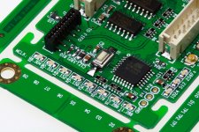
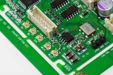
Si570 Clock Board -Native support DACs in dual mono
Si570 clock board was designed be capable to support DACs in dual mono configuration natively.
It has two MCLK u.fl output sockets with drivers independent from each other. Each of the sockets was driven by a dedicated clock driver to ensure high quality low jitter MCLK signals being fed into both DAC blocks. Carefully designed PCB layout matches the impendence to 50ohm transmission lines which optimized to the good signal integrity (SI) driving u.fl coaxial cables.
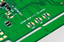
Additional group of u.fl socket footprints of I2S output signals for the second mono block were placed at back side the PCB. Each I2S output signal has its own source termination network to reduce both reflection and cross talking.
To run DAC in dual mono mode, I’m highly recommended using u.fl coaxial cables with same length to guarantee signals arrive at each block at same moment. Please keep in mind, every 1 inch 50ohm coaxial cable will cause roughly 120ps delay on signal!
That’s one of the black magic of a digital cable: vibration and jitter
Ian
Si570 clock board was designed be capable to support DACs in dual mono configuration natively.
It has two MCLK u.fl output sockets with drivers independent from each other. Each of the sockets was driven by a dedicated clock driver to ensure high quality low jitter MCLK signals being fed into both DAC blocks. Carefully designed PCB layout matches the impendence to 50ohm transmission lines which optimized to the good signal integrity (SI) driving u.fl coaxial cables.
Additional group of u.fl socket footprints of I2S output signals for the second mono block were placed at back side the PCB. Each I2S output signal has its own source termination network to reduce both reflection and cross talking.
To run DAC in dual mono mode, I’m highly recommended using u.fl coaxial cables with same length to guarantee signals arrive at each block at same moment. Please keep in mind, every 1 inch 50ohm coaxial cable will cause roughly 120ps delay on signal!
That’s one of the black magic of a digital cable: vibration and jitter
Ian
Attachments
Last edited:
- Home
- Source & Line
- Digital Line Level
- Asynchronous I2S FIFO project, an ultimate weapon to fight the jitter