The EXA board has optical isolation at output.
As far as I know, their first generation product had not an optical but a GMR type isolators of nominal 200 ps jitter.
Hi Ian,
Makes a lot of sense.
I've observed the value of the 32-bit dpll in asynch mode and it varies quite a bit all the time. As one increases the bandwidth of the dpll, the variations get larger.
It may be obvious, but may I ask the question: in asynch mode with the inherent error from the DPLL value, is higher mclk frequency necessarily more accurate? or there is a sweet spot at certain frequency?
The documents of ESS DAC are very limited on this issue. I couldn't find more information about it. But I did do some research on AD1896. I suspect the ASRC principle are similar. ESS is the winner because of both 32bit and higher frequency. AD1896 is 24bith with MCLK only up to 30MHz. The ASRC calculation is based on both bit length and time resolution. So, I think for ESS higher frequency would be help. Async mode sounds good at beginning when you listen to it, but it not as nature and real as sync mode. You will never get back if you already switched to sync mode.
I found 90.xxx and 98.xxx mclk sound more beautiful than 45.xxx and 49.xxx especially at high range with sync mode. But it more sensitive to mclk jitter. If you didn't turn the mclk very well, you can feel something wrong with phase difference on left and right, as well as some strange feeling on sound stage and imaging.
I like higher mclk for ESS, at least for sync mode.
Ian
Last edited:
The documents of ESS DAC are very limited on this issue. I couldn't find more information about it. But I did do some research on AD1896. I suspect the ASRC principle are similar.
I read somewhere before that Dustin used to be a member of AD also.
You will never get back if you already switched to sync mode.
So, did I.
I found 90.xxx and 98.xxx mclk sound more beautiful than 45.xxx and 49.xxx especially at high range with sync mode. But it more sensitive to mclk jitter. If you didn't turn the mclk very well, you can feel something wrong with phase difference on left and right, as well as some strange feeling on sound stage and imaging.
I like higher mclk for ESS, at least for sync mode.
We can buy NDK low phase noise 90.xxx and 98.xxx MHz oscillators at the minimum quantity one.
However, their delivery requires two or three months. As output level is not CMOS but LVPECL, we need an additional level conversion device.
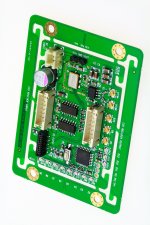
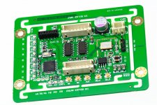
Si570 Clock Board V3.0 – First glance
Si570 Clock Board V3.0 has been running with my system for more than three weeks. The sound was so good. I was pretty much afraid of that the good sound is gone if I disconnect it from my system for taking pictures. That's why I didn’t post it until now. Another psychological problem") .
.
Form V1.0 to V3.0, the design of this small clock board has been revised for three times, as well as three generations prototype PCB. Plus the coming production version, what you will get from the GBIV would be the fourth generation. Sorry for the too much delay, it’s the other side of pursuing perfect. But I'm glad having improvement for each revise. I like the word from a friend: "Good things worth to wait"
There are three main changes implemented to V3.0 from V2.0
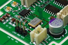
1, Removing on board LOD which is being considered as one of the bottle neck of this clock board. Making it’s possible using high quality low noise external power supply to boost the Si570 performance, as well as experiencing different power solutions.
2, To make it optimized for ESS DAC, inverting the MCLK according ESS application note. But it could be jumped back to normal clock phase for further research or other applications.
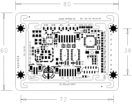
3, Under the help of simulation software and jitter measurement, carefully re-designed the layout, make it enhanced for high frequency low jitter clock generation up to 100MHz
More information about this Si570 clock board will be posted later
Ian
Si570 Clock Board V3.0 has been running with my system for more than three weeks. The sound was so good. I was pretty much afraid of that the good sound is gone if I disconnect it from my system for taking pictures. That's why I didn’t post it until now. Another psychological problem
.Form V1.0 to V3.0, the design of this small clock board has been revised for three times, as well as three generations prototype PCB. Plus the coming production version, what you will get from the GBIV would be the fourth generation. Sorry for the too much delay, it’s the other side of pursuing perfect. But I'm glad having improvement for each revise. I like the word from a friend: "Good things worth to wait"
There are three main changes implemented to V3.0 from V2.0
1, Removing on board LOD which is being considered as one of the bottle neck of this clock board. Making it’s possible using high quality low noise external power supply to boost the Si570 performance, as well as experiencing different power solutions.
2, To make it optimized for ESS DAC, inverting the MCLK according ESS application note. But it could be jumped back to normal clock phase for further research or other applications.
3, Under the help of simulation software and jitter measurement, carefully re-designed the layout, make it enhanced for high frequency low jitter clock generation up to 100MHz
More information about this Si570 clock board will be posted later
Ian
Attachments
Last edited:
Ian,
Waiting for this beauty will be worth without any doubt, for shure!
For putting all parts together, could you possibly put u-fl cables in the GB in a shorter lenght?
Something like two inches long? Have been looking a while for those, but were only available in a pack of hundred!
Looking forward having this clock in my Fifo-setup...
Ed
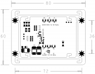
Ian, is that mounting points for an RFI sheild that I can see there?
I know you will explain this later but I will ask anyway, is there an extension to the USART API to control the inverted/normal MCLK or is it hardware jumper only? I ask because swapping these settings with software might allow quicker switching for better A/B comparisons of the settings.
I was doing some work on my Python library for USART control of your Si570 board just last night actually
It looks great!
Cheers,
Chris
Last edited:
looking good Ian, is that a spot for an optional RF fence/cage for the si570?
ed 50mm and 70mm u.fl are available at digikey and mouser (I think) definitely digikey
Ian, is that mounting points for an RFI sheild that I can see there?
I know you will explain this later but I will ask anyway, is there an extension to the USART API to control the inverted/normal MCLK or is it hardware jumper only? I was doing some work on my Python library for USART control of your Si570 board just last night actually
It looks great!
Cheers,
Chris
Yes, it is for the optional RF shield
.Ian
Ian, very nice.
Are the new items listed anywhere?
Thanks,
Since I'm happy with Version 3, I'v already placed PCB order last week for GBIV, as well as Si570 from Silabs. I'll take vacation on March. Hopefully I can finish running GBIV before that time.
Ian
Ian, is that mounting points for an RFI sheild that I can see there?
I know you will explain this later but I will ask anyway, is there an extension to the USART API to control the inverted/normal MCLK or is it hardware jumper only? I ask because swapping these settings with software might allow quicker switching for better A/B comparisons of the settings.
I was doing some work on my Python library for USART control of your Si570 board just last night actually
It looks great!
Cheers,
Chris
Thank you for linking my new post to wiki.
Inverting MCLK achieved by hardware not software, so you couldn't switch it with that easy
.Good to know you start coding the USART, once you get the clock board, you can test them. But a UART isolator is highly recommended for the communication port.
Good night
Ian
Ian,
Waiting for this beauty will be worth without any doubt, for shure!
For putting all parts together, could you possibly put u-fl cables in the GB in a shorter lenght?
Something like two inches long? Have been looking a while for those, but were only available in a pack of hundred!
Looking forward having this clock in my Fifo-setup...
Ed
I'll inquire my supplier to see if I could source some 2" u.fl cables, but the quantity should always be a question...
Ian
Congratulations Ian!
Rally cool looking board. Just a few questions, that I might suspect answers:
1. I see Rxd and TxD contacts - what is the purpose of those? Is that for I2C that could be used with Hifiduino? Since right now Hifiduino does not display rate when used with FIFO, I hope new board will fix that. I think I recall earlier that conversation.
2. Is it possible to use new clock board stand a lone without FIFO? I am just curious since it will be good to have such variable clock board for experimentations. I see no reason why not, besides having something to select frequency, but I stand to be corrected.
Thank you
AR2
Hi AR2,
I think I can answer those for you
1. There is an API doc for the serial port in this post here.
2. The clock board is hard to use separately to the FIFO. I agree it would be nice but the only time that you can change the MCLK is when the input FS changes, within 100ms of 0xC1 event being sent from Ian's Si570. I am reading between the lines but I think this would be reliant on additional comms between the FIFO and Si570 to trigger this event in the Si570 local controller (on Ian's board). Since the FIFO protocols are not published (Ian was asked a few pages back and he has said he is reluctant at this stage to expose these internal workings of the FIFO) there is no way to trigger these events to allow the clock to change frequency separately to the FIFO eco-system. I think it may be possible to use the Si570 as a fixed speed MCLK for other systems at whatever MCLK rate was set previously and rely on async clocking.
I am writing separate control for Si570 already that will be available publicly when it is ready, but will not run on an Arduino. For hifiduino it would need glt to write some additional code for hifiduino to support Si570 comms to calculate the current Fs for output to your DAC LCD/VFD display when using synch mclk (which is what I think you're trying to achieve mainly right?).
Cheers,
Chris
Last edited:
Thank you for linking my new post to wiki.
Nice and quick eh!Thanks for the info.Inverting MCLK achieved by hardware not software, so you couldn't switch it with that easy
Good to know you start coding the USART, once you get the clock board, you can test them. But a UART isolator is highly recommended for the communication port.
Lucky you already designed a board that supports the isolator hey!
Chris
Looking good Ian! A wish for the GB4. Please gather all things possible to be ordered so that one don't need to visit GB 2 and 3 for isolator, regulator and cables etc...
For iso. and reg., please provide assembled.
Can Si570 still be regarded an embedded solution i.e. no controller is needed in order to play music on different sampling rates?
/
For iso. and reg., please provide assembled.
Can Si570 still be regarded an embedded solution i.e. no controller is needed in order to play music on different sampling rates?
/
TNT,
Si570 external controller is only for either custom mclk at each Fs or to all an arduino to display current Fs, xFs and mclk on an LCD or similar.
There is no need for external controller for normal operations. There is a link in the Si570 section of the wiki to an earlier post by Ian that lists the standard mclk frequencies selected by Si570.
Hope that clarifies things for you
Chris
- Home
- Source & Line
- Digital Line Level
- Asynchronous I2S FIFO project, an ultimate weapon to fight the jitter