Hi jcx,
I don't miss your point because I normally use a cascoded (double) current mirrors in the collector loads of the complimentary symmetry LPT in my designs. Designing audio equipment has been part of my everyday life for 37 years.
I have seen many designers deliberately designing with an imbalanced long tail pair, ESP being one and Hugh also does that. Keeping in mind that the AKSA 50 has been to my knowledge a well received and much appreciated product for its particular sonic qualities.
As Nelson says everything does not appeal to everyone, but earlier in the thread Hugh stated that he wanted to produce the characteristic AKSA sound and to retain this "sound" one has to stick to a particular topology that has worked for his audience.
Now have a look at how much has been said in this thread and what has changed between the schematic in the first posting and the current posting.
Although it has been much discussed, Hugh has only made very minor adjustments to his original design and that I believe he is doing because he wants to retain the characteristic sound that his amplifiers has become known for.
Believe me every change made, no matter how silly it seems at the time makes a difference in the sound character of equipment. The purpose of this thread was to offer a typical AKSA sound, not to develop a new super amplifier without any predictable sonic result.
I have in the past made a headphone amp using the almost the identical topology and in the early stages of this thread, I modified it to look like Hugh's amp. It is unconditionally stable even with capacitive loads of 10 uF. There is no hint of oscillation. It is stable over a wide range of temperatures (without the diodes mounted even close to the heat sink) compensation for environmental temperature is quite sufficient. It has a low output impedance, very flat freq/gain characteristic, and very low phase shift, exceeding that required for audio reproduction.
At the power levels required to drive headphones the THD is quite sufficient. 2nd and 3rd order inter-modulation products may show up more readily depending on the complexity and level of the input stimulus, but this is all in-line with what Hugh is trying to share with those subscribing to this thread regarding his AKSA sound.
Hugh, I and many other designers do not share sonic expectations and I doubt if we share the same music genre, and therefore we design amplifiers differently and obviously they will sound very different, neither better nor worse, only different.
Hugh found a sonic fingerprint in AKSA that probably appeals to a broader listener base than those following more empirical design rules.
It is all about subjectivity, the sound and perception. People buy products based on aesthetics, what it feels like and what others say about it. Very few customers are inclined to scrutinise the design, verifiability, traceability or processes the product followed before entering the market.
Kindest regards
Nico
Interesting. Design elegance/low THD versus simplicity and a rather unconventional attitude to distortion. The tried and true approach perfected over 60 years of solid audio engineering.
JCX, I have built both circuits, with and without CMs, and with bootstraps and CCS.
Based entirely subjectively on the basis of SQ, I choose bootstraps, and imperfect LTP resistive feed.
The object of the exercise is as follows:
1. Simplicity with low parts count.
2. Low cost.
3. Good stability margin into a variety of cans.
4. Best possible sound quality.
#4 is entirely subjective. If I were intending to aim for lowest possible THD20, ease of setup, and good specs, I would do exactly as you suggest. It would, in fact, be a no-brainer, and would deliver a competent, well engineered audio amplifier.
I have done this many times in the past, and the result has been mediocre SQ which does not stand out in any way and which certainly does not impress most non-technical audiophiles. I believe I can explain this, but I would say that if you want it to sound good, build it way I've suggested. If you believe this is nonsense, as many do, then quite simply don't build it. It is difficult enough to design anything in audio, harder still if every step requires long justification before even a prototype is built and subjectively assessed.
If you want good specs, and an amp that sounds like every other perfect measurement Self amp, then your suggestions are appropriate and effective. But it will sound like an ice pick in the ears......
If you disagree, you can throw all the engineering at it that you like, and you may in fact do that. I do thank you for your courtesy, you could have ridiculed the design, but in fact my AKSA is based on this approach and the sound of this amp is something very special.
I must build the circuit ASAP to check that it sounds precisely as I expect it to.
It will NOT have lowest possible THD. In fact, H2 and H3 will be quite in evidence. But it will sound wonderful. And lowest possible lag compensation will have a lot to do with that.
I won't comment further in this thread until I've built and listened to it; might take a few days, I'm incredibly busy at present.
Thank you for your input.
Cheers,
Hugh
Hi Everyone
I found this thread a couple of days ago and have now read quite a bit of it. It has been very interesting and I have learnt quite a lot, the design seems to promise very good performance for such simplicity. I have not done any electronics for a long time and am thinking about getting back into it. I had not come across simulating the loop gain before, it looks very useful. I have also been interested in the comments about the long tailed pair, both with respect to lowering the feedback resistance and the effect on the LTP of adding emitter degeneration to the VAS.
Am I right in thinking that the input impedance of the LTP changes as a function of the differential input voltage due to the non-linear transfer characteristic, resulting in the base currents changing in a non-linear way with respect to the input voltage and this is why lowering the feedback resistance lowers distortion? (R8 is in parallel with a changing impedance so reducing R8 lessens the effect of the changing impedance on the feedback potential divider)
The distortion measurements have all be based on 1V into 30 ohms. With a loop gain of 35dB there will be about 18mV input voltage to the LTP and its gain varies by about 2%. However to put the same (potentially deafening) power into 300 ohms you need about 56mV input and the gain of the LTP will change by about 10% between the peak on the signal and where it crosses 0V. I was wondering how the affects the distortion of the amp driving higher impedance loads
As I say its a while since I have done anything like this any help in understanding the design will be most welcome.
I'm new to diyaudio.com and have been impressed with how friendly everyone is.
Best wishes
Phil
Welcome aboard Phil! You're right, this is a very freindly place. A great bunch.
Yes, a very interesting thread...... learning heaps, not just about how stuff works... I'm really getting a lot out of the discussions about the numerous compromises that are necessary to optimise the circuit to meet the design objectives.
I'm really looking forward to hearing about the first builds....can't be long now.
Last edited:
Hi Phil. I'm glad you enjoyed the thread. DIYAudio is a place that will reward you for being creative, open-minded and inquisitive, as well as having humility to work to the benefit of the whole.
You seem to get the idea but I'll explain.
The general consensus on the LTP is that each side should be balanced, both transistors should have the same source impedance (at AC and DC). This means that the offset current on one side is canceled out by the offset current in the other. However, these transistors also have junction capacitance, going from 4p to 14p depending on Ft and Vceo. Because of this, the feedback voltage divider has a virtual nonlinear capacitor to ground, coupled with what error is not canceled between the two transistors. This nonlinear input characteristic causes distortion depending on the source impedance. Lowering this impedance decreases the distortion, as well as high order harmonics partly amplified and partly created by the capacitance and Ib error.
My solution to this is to decrease both feedback resistors proportionally to retain the same voltage divider ratio. So R7 would be 1k and R8 would be 150R. (the input side resistors aren't necessary to change although there would be similar benefits, but unfortunately there will be a little offset since the DC impedance at both sides is not the same, so the DC base current offset doesn't cancel)
One thing to note however is that this mod has different affects on different amplifiers, depending on the LTP input impedance (a CFP LTP would have far more linear input current and so the affect would possibly not be noticeable or even be worse). High-OLG amps may not have much of an affect on overall distortion but generally high-order harmonics are reduced, and stability is increased.
Another benefit of this is that we would need to increase C4 in order for it to have the same affect. The benefit of this is that at 10p, trace capacitances have a greater affect and possibility to cause issues. With a larger capacitance value trace capacitances become less important and worrisome.
- keantoken
Very nicely explained, KT.
You could also say that the input is normally fed from very low impedance, and this should match as close as possible the impedance of the drive on the fb side. This source impedance is, of course, very close to the value of the shunt resistor in the fb network. And clearly we should match the input devices, so that their betas and Vbes are the same in the balanced position.
Have you considered what happens to the distortion artefacts if the input impedances of each node are markedly different? Or what happens to the output impedance of the amp?
Have a bit of a sim and let us know, if you are interested of course!
Cheers,
Hugh
I'm working on it, Hugh.
I just had a thought...
Headphones have a range of different impedances, unlike loudspeakers. The most important factor to distortion is how much current is going through the load, voltage is not so important (voltage has less of an affect on transistor linearity than current, if I understand correctly. Voltage error mechanisms are Early affect and Varactor Cbo). This amp will sound different with different headphones because distortion will vary not depending on the wattage through the headphones, but the current (lower impedance needs more current for listening volume while high impedance needs more voltage).
To make the amp more consistent between output headphone impedances, is it advisable to use a current feedback approach, where it is the current through the load that is measured, not the voltage? This way, the amp would be more "load invariant" between headphones save for CMRR and Early affect related distortion. (Is it just me, or are early affect, CMRR and Varactor Cbo IMD-related error mechanisms? If so, voltage feedback is, theoretically, "sonically preferred")
- keantoken
Last edited:
I don't believe so, since both current and impedance (Irms squared x Impedance) defines the power, so relying solely on current would not be appropriate to acoustic output.
This is no different to monitoring V (which is what the voltage feedback network does anyway) since P = Vrms squared/Impedance, again, the impedance has linear influence.
Voltage feedback is 'sonically preferred' as you put it because the vast majority of drivers are designed for it. A current fb mode would generate a prescribed current output for a set input voltage, a transconductance amplifier, and this would mean that any variations in impedance would result in greater or lesser voltage application without regard for the voltage input.
That would distort seriously unless a purpose designed speaker driver were used, one with near on constant impedance across the entire frequency range.
Cheers,
Hugh
I see. I'll have to try it one of these days to amuse myself. I've been fascinated with the idea of current feedback for some time. (maybe current feedback is desirable for electrostatics since they are principally capacitive, while loudspeakers are principally inductive. Although as you say, they have been designed for voltage drive)
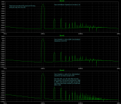
Here is the result. I used 2.2k and 22k feedback and shunt resistors to provide a voltage gain of exactly 10, then modified as described by dividing these values by 10 (giving 220R and 2.2k for either input or feedback side).
- keantoken
Here is the result. I used 2.2k and 22k feedback and shunt resistors to provide a voltage gain of exactly 10, then modified as described by dividing these values by 10 (giving 220R and 2.2k for either input or feedback side).
- keantoken
Attachments
Last edited:
Reading your post again maybe you missed my point.
My observation with amplifiers in voltage feedback mode is that distortion doesn't increase with voltage output, but with current output. As long as the output current is the same, distortion will be close to the same regardless of output voltage because current has more affect on linearity of the VAS and OPS than voltage does. Because volume is not entirely dependent on voltage, the amplifier will be putting more current through lower impedance headphones in order to produce the same volume. This means that the amplifier will produce higher distortion into low impedances than into high impedances. However if we use current feedback, the amplifier will output the same current for any given headphone, regardless of voltage, which will make the amp itself more consistent between headphones. I'm not suggesting that it would make the headphones themselves perform better.
I'm not suggesting we make a change, since as you said the mass majority of transducers are designed for voltage feedback. I just wanted to clarify.
And, I have to admit I made a mistake simulating the feedback network impedances. I didn't increase the phase lead cap accordingly when I lowered the feedback impedance, which is the reason the simulation is so optimistic. If I change the cap to its proper value, 50pF, there is only slight improvement.
So the increase in performance on the bottom graph is actually due to the phase lead cap being lower than it's proper value. Hugh, you said that having lowest possible lag compensation increases SQ, and these simulations reflect that. With 50pF being the "effectively same" amount after this mod, we can decrease it to say 33, 22, etc. whereas before trace capacitances were an issue and we would be using very low value caps. Is it reasonable to decrease the phase lead cap now providing we decrease feedback impedance as shown? I could tell you myself if I could get the loopgain simulation to work, but I can't.
- keantoken
Last edited:
Member
Joined 2009
Paid Member
[...] having lowest possible lag compensation increases SQ[...]
I listened to my TGM (similar topology) with different compensation capacitor values and I could hear a difference. I made the changes to only one channel and I used the same piece of music to compare changes. The lowest value was not the best SQ, neither was the highest. The changes were quite subtle, but it was still noticeable. Had I not been making the comparisons I may not have identified that the sound was less than great but as a result of the experiment I settled on a middle value of compensation cap.
The compensation cap is often painted as an evil device but I've heard such comments about output capacitors too - there's often a good body of experience that supports these claims but the details always reveal exceptions. In the case of capacitors I believe a lot of it was born from poor quality capacitors of past which pale in comparison with modern capacitors. With compensation caps there are details to think about. For example, the VAS device has an internal Miller capacitance, which is a very poor capacitor since it is formed out of a depletion region in the semiconductor it varies with bias - it's non-linear. It also has charge moving through a medium with resistance so it has a poor dielectric. Adding a compensation capacitor for me is rather like adding emitter degeneration resistors - the external component has much better performance than the internal one. In the case of emitter degeneration it 'swamps' a non-linear emitter resistance and by providing local feedback it improves linearity. In the case of Cdom it can 'swamp' the internal capacitance and since it also generates local feedback it also linearizes the VAS.
I say it's time to accord some respect to Cdom !

Last edited:
I understand your comments regarding miller and lag through the simulator. There seems to be an optimal value/ratio between lag and miller compensation. You are right, I need to take more note of the affect of such compensation (especially as its affect is strongly situational, which means I don't yet understand completely the underlying mechanisms).
I'm playing with an incredible new LTP-based topology, and it shows similarly incredible promise. I have a properly compensated headphone amp simulated right now, and the OLG only begins to roll down at 10KHz, while the distortion at 3.5V pk-pk into 32 ohms is only .0003%! This, in only 6 transistors, not counting two CCS, which have two transistors each. The greatest thing about this topology is that it DOESN'T create HF upfolded harmonics - it is so deadly fast, extremely precise, and superhigh gain, that even in class B it is comparable with AB amplifiers I've designed in the simulator. So I have, ready for prototyping, a super low-THD class B headamp which only draws about 6mA idle current - I was aiming for a battery-friendly headamp suitable for long walks with an Ipod. Boy, do I feel lucky (the idea lacks real-world confirmation but I don't see any issues at this point). Unfortunately I've had to add it to my long list of future prototyping projects. /:
Anyways, enough bragging. I really feel like I've learned an enormous amount from this thread, knowledge without which I would not have devised my aforementioned discovery, and with which I feel much more competent as a designer. One main factor is that I simulated everything instead of simply guessing and theorizing. So really I am incredibly indebted to DIYAudio and all who participated in this thread. Thanks!
- keantoken
Last edited:
Member
Joined 2009
Paid Member
Excellent! after all the work you have contributed it does seem timely to strike out with a full design of your own. The key is to build it and let us know how it sounds (with a thread of your own). I'm afraid I have time and brains only to add ideas to what has gone before and even then it seems everything has already been invented. But it's fun all the same !
What I observe is that yes, almost everything has already been invented and used... But not perfected. There are a million different principle functions a single transistor can perform, and a lot of so-called "creativity" is knowing all these forms and their DC, AC and power characteristics. Then you can look at an application, look at what principle function is missing or needed, and so you start from a one-transistor solution and go upwards if needed. Ever notice how creativity often takes the form of a single transistor added in a funny way?
When I was not very good at electronics I had lots of crazy ideas. I tried them all but for lack of skill and simulation knowledge, I wasn't able to give them the attention they deserve. What I'm finding now is that some of my old ideas were pretty good and unique too, and I'm going back to old designs and updating them. I'm finding that my intuition was usually right, even though I didn't have the skill to implement it.
What I need is to develop a product I can sell to help fund my future endeavors. I can still release the information publicly but before doing so I want to send prototypes around to different members in good standing with the DIYAudio community that can describe the performance in relation to other amps they've had. Once I know I've got something special, I would release it.
- keantoken
You will find when you start building circuits and testing your ideas that in the real world things are just slightly different, and that any and all changes you make to a circuit will be audible. You will also blow up lots of devices; this is quite normal. The circuits may not measure differently on an AP1, but they will sound different. This takes a long time to reconcile, but is a fascinating journey.
KT, you gotta get started right away...... you owe it to the world!
Hugh
KT, you gotta get started right away...... you owe it to the world!
Hugh
Member
Joined 2009
Paid Member
[...] What I'm finding now is that some of my old ideas were pretty good and unique too[...]
I agree, there is a benefit if sometimes you don't know 'too' much as this kind of baggage can constrain your thinking. It allows you to consider things that an 'old hand' might dismiss out of mind before it really got going.
I also have a sketch book with some strange things in it, I should start sending them in your direction
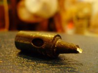
AKSA, I'd be happy to get started, but I'm still missing several key things, such as assorted high-watt resistors, an assortment of capacitors, and some more veroboard would help. Not to mention I need several hundred transistors (as you point out) of the various types. I also have to get a better soldering iron or at least a new tip, see attachment (is this okay to solder with!?). It takes a very large investment just to get enough parts to start working, and then I have to find some way to keep the money coming in.
Bigun, I'd be happy to see your ideas if you don't believe you can do much with them. But if you had a strong sense of intuition when making them, I would be careful. This sense of intuition was my gateway into electronics and in my opinion your intuition should be kept to yourself - it means that you have very special insights, for whatever reason, into that specific circuit more than most people. It may just be a funny feeling now, but later you might "see the light" after learning more.
- keantoken
Attachments
Michael,
They look fine. 200V, 100mA, Cob 1.9-2.3pF, good beta linearity, they look good.
The 3423 however is specifically designed for audio, where these devices you suggest are used for high definition CR tubes on TVs and monitors. I have used video devices in audio (BF469/470, 2SC1819) and they work well, but I suspect that the greater beta linearity of the audio variant and it's very flat Cob from 0.5 to 100V Vce (1.8 to 4pF) might be the clincher.
Cheers,
Hugh
- Home
- More Vendors...
- AKSA
- Aspen Headphone Amp