I want you to learn of these things my friend:-
Decorum. Restraint. Dignified Enjoyment. Honour. Tolerance. Community.
This is the way of the East.
Greetings from this wonderful island, Japan, on this beautiful late summers evening, as a sip my warm sake . . .
Decorum. Restraint. Dignified Enjoyment. Honour. Tolerance. Community.
This is the way of the East.
Greetings from this wonderful island, Japan, on this beautiful late summers evening, as a sip my warm sake . . .
Last edited:
I only follow suggestions after i test them Andrew... also
i am moved by motivations...my customers (DIY) are my targed...they ask and i move....In the reality, brazilian friends asked me..that's what moved me to change things, not your suggestions.
I use to follow suggestions from my mind... sometimes the rusted machine works.
But go dreaming was you the reason why that moved me... only by magic as i used not to read you..so..could not see your suggestions.... believe was you...if this feeds your soul.
From time to time i go reading you..to check your mood if you're in the 5 percent positive moments.
regards,
Carlos
Last edited:
Boys.... i am applying some torture on Blame MKII.
But really i am lazy these days after surgery...i feel some small pains when moving too much.... so...i will not connect several supplies in parallel (Dc out in parallel)... because of that, i have no power from the supply to feed 2.5 ohms loads or even a little bit less than that... reason why i made test only to 3.0 ohms (discounting my meter cable errors during measurement and parallel resistances behind the huge speaker).
It seems safe to 3.0 ohms.... i am really not sure if will survive to 2.5 ohms or less...so...because lazy...i will specify the unit to 3 ohms minimum load...... it is reasonable...others can try lower impedances....well.... make it under your own risk..i do not believe in simulators datasheet or graphics.... simulator said OK!....but not testing real life i do not believe and i cannot guarantee good results.
YouTube - Torture on Blame MKII continues.,.200W - 3 ohms
regards,
Carlos
Board was not tested Azmi... but the circuit is OK!
I will forward you some small modifications as soon as you start to build and publish some pictures.
I am not talking about the chance to have oscilations.... but the change to have something missed there... both things are possible, despite the one made the board, Alexmm, is very good...but we..humans, we fail.
regards,
Carlos
Boards are ready to go...layout is ready..also tests are doing fine
So, no troubles to the release in December, 24th.
I had to take some decisions:
First was one board to all models.... Dx Blame ES/ST, Dx Blame MKII and Dx Blame MKII Supercharged.
Second, silk screen forced me to use a standard transistor to all models, so, at the silk screen we have 2N5401 and 2N5551 indications...but people can use BC546/556 (suggested) in the place of the high voltage ones, just inverting the way they will go to the board.... silk screen indicates 2N5401 and 2N5551, and these ones works too...it will be up to you folks, the ones to use.
Dx Blame ES/ST and Dx Blame MKII uses 35 volts (42 volts maximum)..the Dx Blame MKII Supercharged will use higher voltage...maybe 55 or 63..i am still thinking about and testing options.
Almost all parts will have part numbers and also their values printed inside resistance rectangles (covered by the resistance after assembled), to make it easy and faster to assemble.... some parts are different to each model, and these ones, the different ones, will have part identification numbers and no values....values will be obtained from a chart that will be published the same day i will publish schematics, layout and the chart of part's substitution values.
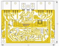
I am showing you just the upper part.... i am very happy with this board..finally i could have a board that matches, entirelly, my needs... well... this is a natural progression.... i was waiting 7 years to have it my way..finally this one is "my way".
This one is 100 percent approved, i had not to negotiate, Mitchel made my way..... a matter of coincidence..... it is his way too... maybe cause we are both Brazilians..no troubles...he made with pleasure and had not to make violence with himself.
regards,
Carlos
So, no troubles to the release in December, 24th.
I had to take some decisions:
First was one board to all models.... Dx Blame ES/ST, Dx Blame MKII and Dx Blame MKII Supercharged.
Second, silk screen forced me to use a standard transistor to all models, so, at the silk screen we have 2N5401 and 2N5551 indications...but people can use BC546/556 (suggested) in the place of the high voltage ones, just inverting the way they will go to the board.... silk screen indicates 2N5401 and 2N5551, and these ones works too...it will be up to you folks, the ones to use.
Dx Blame ES/ST and Dx Blame MKII uses 35 volts (42 volts maximum)..the Dx Blame MKII Supercharged will use higher voltage...maybe 55 or 63..i am still thinking about and testing options.
Almost all parts will have part numbers and also their values printed inside resistance rectangles (covered by the resistance after assembled), to make it easy and faster to assemble.... some parts are different to each model, and these ones, the different ones, will have part identification numbers and no values....values will be obtained from a chart that will be published the same day i will publish schematics, layout and the chart of part's substitution values.
I am showing you just the upper part.... i am very happy with this board..finally i could have a board that matches, entirelly, my needs... well... this is a natural progression.... i was waiting 7 years to have it my way..finally this one is "my way".
This one is 100 percent approved, i had not to negotiate, Mitchel made my way..... a matter of coincidence..... it is his way too... maybe cause we are both Brazilians..no troubles...he made with pleasure and had not to make violence with himself.
regards,
Carlos
Attachments
Last edited:
A needed tribute to Todd Johson, our TAJ, will be printed into the board
As all further layout developments started from his excellent work...so, despite some upgrades made, he deserves to be pointed as the pionner in this layout style.
regards,
Carlos
As all further layout developments started from his excellent work...so, despite some upgrades made, he deserves to be pointed as the pionner in this layout style.
regards,
Carlos
Attachments
Last edited:
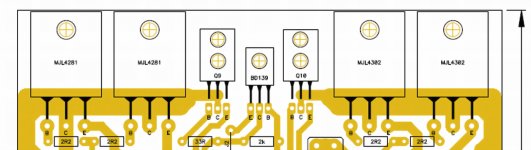
re post 28,
notice how close the supply rails come to each other at the collectors of Q9 & Q10.
This is where the HF decoupling should be placed. There is space between the transistors and traces on the top (or links if single sided) will pass across the other traces. Or use the empty part of the PCB under the legs of the bd139 Vbe multiplier for a bottom side trace.
The biggest problem left is the long distance ~90mm to the nearest point on the Power Ground.
Last edited:
I strong appreciate Doctor Self dear AndrewT...but despite that
i do not disengage my brain while reading his book.... try one and other way and you will see that there's no difference.
There are some instructions in his book that shows me Mr. Self has an explendid mood..he wrote things to feed illusions too..he may be laughing about people following this alike a religion.
Take some English high end designs made by him..and you will see the signal is not beeing captured in the place he suggested in his book....even himself abandoned the practice.
regards,
Carlos
Attachments
Last edited:
AndrewT said:This is where the HF decoupling should be placed. There is space between the transistors and traces on the top (or links if single sided) will pass across the other traces. Or use the empty part of the PCB under the legs of the bd139 Vbe multiplier for a bottom side trace.
The biggest problem left is the long distance ~90mm to the nearest point on the Power Ground.
Hi Andrew. We could just solder one end of a 100nF capacitor directly over the colector terminal of Q9, and have the other end wired to ground. THe same procedure should be done to Q10. I don't think there's space to have this capacitors on the board, because it's single sided.
This is a myth Mitchel, based in the standing wave ratios measured in Radio Frequency
There's some folks that undertand that alike spiritualism.... your capacitors will not capture the spirit!.. if not placed in the Universe center...exactly in between the blue and the orange first strip left electrons..that one have one boot brown and other boot black.
ehehehehehehe")
They want the junction, the spatial point...and this is alike the vaccum gab in between two atoms.... one turning clockwise and other counter clockwise and you should install your tip of solder exactly in between them... something alike the universe center or the black hole's suction point...cannot have resistance and micro ohms are their worries... you will never succeed if start a discussion with spiritualists..they say spirits exists despite you cannot see them..but they say YOU cannot see them because you have not faith.... they you say you are ignorant.... the blindness of faith absence.
Thank you anyway...but the capacitor will cause a dissarange in the universe stability and the Orion Constelation may detach spelling left handed Omega waves that may heat the North Pole...and this explains the Global warmth.... you see?.. they are rigth...we have global warmth!
I am kidding...but all that stuff is funny.... and i cannot be reading that without laugh.
You, as always, behave very kindly, despite this will never work...they want the board modification capturing the feedback exactly in the mid point... with short lines and so on....i do not agree with such kind of modifications because it is non sense....if you give them room, they will point almost the entire amplifier defective, wrong and with flaws..good are the invisible ones they have made!....but what others makes are always bad...you know.... they are the universe center.... whole mankind is wrong, unless follow their instructions.
- "algumas coisas estão abaixo do nosso limiar de percepção, coisas para instrumentos Nabuco..alguns se preocupam com isso porque são detalhistas mesmo...se ouve ou não ouve nem interessa pra êles... não esquente senão ficas maluco que nem.... "
There are things, effects that are below our perception...things only instruments can detect and show..some folks have worries because obsessive personalities... a strong feeling of unsafe about everything...that anything is perfect enougth.... 0.002 is different than 0.0019..when you cannot perceive such difference...you know..worries about non important things...they're this way and there's no hope for them to heal without years of Psycho therapy.
If you can listen or not some subject... this is something they do not mind..what matters are their menthal confusion...the enormous need to organize the external world to compensate their internal self confusion......if you give them attention, overheating your brain because their ideas, you will be ... alike them.... those guys are rarities...very exotic minds.... very few guys gladly.
regards,
Carlos
There's some folks that undertand that alike spiritualism.... your capacitors will not capture the spirit!.. if not placed in the Universe center...exactly in between the blue and the orange first strip left electrons..that one have one boot brown and other boot black.
ehehehehehehe
They want the junction, the spatial point...and this is alike the vaccum gab in between two atoms.... one turning clockwise and other counter clockwise and you should install your tip of solder exactly in between them... something alike the universe center or the black hole's suction point...cannot have resistance and micro ohms are their worries... you will never succeed if start a discussion with spiritualists..they say spirits exists despite you cannot see them..but they say YOU cannot see them because you have not faith.... they you say you are ignorant.... the blindness of faith absence.
Thank you anyway...but the capacitor will cause a dissarange in the universe stability and the Orion Constelation may detach spelling left handed Omega waves that may heat the North Pole...and this explains the Global warmth.... you see?.. they are rigth...we have global warmth!
I am kidding...but all that stuff is funny.... and i cannot be reading that without laugh.
You, as always, behave very kindly, despite this will never work...they want the board modification capturing the feedback exactly in the mid point... with short lines and so on....i do not agree with such kind of modifications because it is non sense....if you give them room, they will point almost the entire amplifier defective, wrong and with flaws..good are the invisible ones they have made!....but what others makes are always bad...you know.... they are the universe center.... whole mankind is wrong, unless follow their instructions.
- "algumas coisas estão abaixo do nosso limiar de percepção, coisas para instrumentos Nabuco..alguns se preocupam com isso porque são detalhistas mesmo...se ouve ou não ouve nem interessa pra êles... não esquente senão ficas maluco que nem.... "
There are things, effects that are below our perception...things only instruments can detect and show..some folks have worries because obsessive personalities... a strong feeling of unsafe about everything...that anything is perfect enougth.... 0.002 is different than 0.0019..when you cannot perceive such difference...you know..worries about non important things...they're this way and there's no hope for them to heal without years of Psycho therapy.
If you can listen or not some subject... this is something they do not mind..what matters are their menthal confusion...the enormous need to organize the external world to compensate their internal self confusion......if you give them attention, overheating your brain because their ideas, you will be ... alike them.... those guys are rarities...very exotic minds.... very few guys gladly.
regards,
Carlos
Last edited:
We have arranged, me and Mitchel, another board style, more rational in my point of
view.... more modern and more simple... we have detached the board assemblage from a computer screen (part's list) or a piece of paper (BOM).
I do think...and i always had that idea, that is not very good to have a part list and to print R1 (for instance...means Rx) in the board...this will be helpfull while debugging...but really, nice amplifiers, assembled without mistakes, will never ask by debugging, and they are turning more and more rarities....but, anyway, we need a reference number, not to be saying:
- "search that transistor that is over the BD139 and below the XXXX transistor, that MJExxxx, positioned left low board side."
Of course, it is much better, and easier, to say....
- "search for Q12"
So, we need that stuff, but we do not need, in a mandatory way, these indications to be printed over the board as silk screen.... we can have an image, a xerox copy, a printed copy, a word doc, a pdf or something alike to be used "if needed"..... so...board will have this companion, xerox copy will go together and will be helpfull if you face troubles.... when to search for mistakes.
But the values are needed and detach you to be in front of the computer, let you free from copies, pdf, word docs and so on.... printing values over the board, as silk screen, not only they will be covered by the resistance (as an example) but will be needed for you to select parts and to populate your board....the resistance value can be printed inside the rectangle that indicates resistance....so... you see that Dx people use to engage brain and not go following old rules without think about if the old style is good, if no good..when it is good and when and where it is no good.
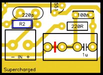
This way, values, indications of parts alike 2N5401, 2uf, 100n, 220p...all this will be seen in our board.... because we have no transistor 2N5401 with Q1 printed on it..also we have no 100n capacitor printed C23 on it!... so... we are removing unnecessary non sense steps in the procedure.
Parts that have not fixed value, for instance. VAS emitter resistance, that has one different value to each model.... this one and some others will have part number indications, as people will use a chart to select it because each model will have their proper values...this way, a single board, that can be good for 4 models.
So...this way there's no "Supercharged board"..no "Blame ST board," no "Blame MKII board"...we gonna have "Blame board"
This is something i always wanted to do. but i always have faced oposition from friends that where producing layout..... now i got it..finally.
I do not know how to use Eagle, also i do not want to learn...i do prefere other doing that...i am better to do amplifiers.... and it is better to each one of us to be doing what we know how to do.
There are folks that feel happy doing layout..when i hate to do that...make sense them to make and to obtain pleasure then uncle charlie to be upset with that stuff.
So, as you can see in the image attached below, we gonna have few indications printed over the board as silk screen.... the Designer name, the Layout reviser name, the Layout original designer name and models the board can be used to..... parts will cover the indications...board will not look alike an outdoor, will have class and elegance.
regards,
Carlos
view.... more modern and more simple... we have detached the board assemblage from a computer screen (part's list) or a piece of paper (BOM).
I do think...and i always had that idea, that is not very good to have a part list and to print R1 (for instance...means Rx) in the board...this will be helpfull while debugging...but really, nice amplifiers, assembled without mistakes, will never ask by debugging, and they are turning more and more rarities....but, anyway, we need a reference number, not to be saying:
- "search that transistor that is over the BD139 and below the XXXX transistor, that MJExxxx, positioned left low board side."
Of course, it is much better, and easier, to say....
- "search for Q12"
So, we need that stuff, but we do not need, in a mandatory way, these indications to be printed over the board as silk screen.... we can have an image, a xerox copy, a printed copy, a word doc, a pdf or something alike to be used "if needed"..... so...board will have this companion, xerox copy will go together and will be helpfull if you face troubles.... when to search for mistakes.
But the values are needed and detach you to be in front of the computer, let you free from copies, pdf, word docs and so on.... printing values over the board, as silk screen, not only they will be covered by the resistance (as an example) but will be needed for you to select parts and to populate your board....the resistance value can be printed inside the rectangle that indicates resistance....so... you see that Dx people use to engage brain and not go following old rules without think about if the old style is good, if no good..when it is good and when and where it is no good.
This way, values, indications of parts alike 2N5401, 2uf, 100n, 220p...all this will be seen in our board.... because we have no transistor 2N5401 with Q1 printed on it..also we have no 100n capacitor printed C23 on it!... so... we are removing unnecessary non sense steps in the procedure.
Parts that have not fixed value, for instance. VAS emitter resistance, that has one different value to each model.... this one and some others will have part number indications, as people will use a chart to select it because each model will have their proper values...this way, a single board, that can be good for 4 models.
So...this way there's no "Supercharged board"..no "Blame ST board," no "Blame MKII board"...we gonna have "Blame board"
This is something i always wanted to do. but i always have faced oposition from friends that where producing layout..... now i got it..finally.
I do not know how to use Eagle, also i do not want to learn...i do prefere other doing that...i am better to do amplifiers.... and it is better to each one of us to be doing what we know how to do.
There are folks that feel happy doing layout..when i hate to do that...make sense them to make and to obtain pleasure then uncle charlie to be upset with that stuff.
So, as you can see in the image attached below, we gonna have few indications printed over the board as silk screen.... the Designer name, the Layout reviser name, the Layout original designer name and models the board can be used to..... parts will cover the indications...board will not look alike an outdoor, will have class and elegance.
regards,
Carlos
Attachments
Last edited:
Well done Carlos 
However, maybe some output power comparison chart would also be fine, cause now we will soon have many amplifers to choose from
Maybe it could look like this...
Blame ST: 50W / 8ohm, 100W / 4 ohm, minimum impedance 4 ohm
Blame MK II: ? / 8ohm, ? / 4 ohm, 200W / 3ohm, minimum impedance 3 ohm
Blame Supercharged: 100W / 8 ohm, 200W / 4 ohm, minimum impedance 4 ohm
All right Supernet.
Dx Blame ES/ST - 35 volts supplies - 50 Watts at 8 ohms and 100 watts at 4 ohms
Dx Blame MKII - 35 volts supplies - 50 Watts at 8 ohms, 100 watts at 4 ohms and 180 watts at 2.5 ohms
Dx Blame Supercharged - 35 volts supplies - 100 watts at 8 ohms,and 200 watts at 4 ohms)
In the case of the Blame Supercharged, it will produce a little bit more power.
regards,
Carlos
We are searching for board's supplier...manufacturer that can produce with
International quality...something that can match the Internacional quality..we are also searching for features versus price.
The main idea is to find a supplier, in Brasil, that can match quality and price, not to go competing with Rudi or another board group buy to be opened in the future.
This way, despite we gonna reduce orders from Brasil, we gonna have international price...now we are searching no more for low price..but for high quality.
The Brazilian boards, these ones sold to the Brazilian group buy, had anything special..only fiberglass, sanded surface to guarantee the silk screen not to wear out.... the silk screen was not thick, not special, nor very clear, nor very focused or very good..just reasonable for the price (low)
Our idea, is no more quantity, but quality, we want less builders,but the ones appreciate quality, these ones are able to use two supplies, the ones are not interested to save money in the supply, boards, or enclosure.
We already had more than 100 builders...so.... we are satisfied and we want now to improve quality.
We are still working.
regards,
Carlos
Last edited:
We gonna try to order here in Brazil..this will avoid shipment costs
and shipment delay....internal mail in Brasil can arrive next day before 10AM.
Also we can make agreements directly with the production manager, using telephone and in Portuguese...we will not be talking with a salesman, but with the one will really do the real job together some employees and some machines.
Some folks have suggested me other sites, other countries and other board manufacturers to help us...i am explaining, in advance, to others that have the intention to help in this same way..that we have our reasons to produce here.
Easier and faster...these are the main reasons to order here..about quality we can have (at least we hope) achieve the same international standards of quality.
Thank you folks, the ones sent PM.
regards,
Carlos
Did you mean to type?
Dx Blame Supercharged - 50 volts supplies - 100 watts at 8 ohms,and 200 watts at 4 ohms)
Did you mean to type?
Yes, I think he meant 55V actually for that last one, Andrew.
Also, I'm not clear on which transistors are Q9 and 10 you were talking about -- the drivers next to the output transistors? And the power ground is 90mm from what? Can you clarify that last bit? Thanks. Just curious.
Carlos, I appreciate the tribute, but this gold layout is much different/improved over my green one. Putting my name on it seems a little uncomfortable to me. Mitchel's name should be on it.
..Todd
Last edited:
- Status
- This old topic is closed. If you want to reopen this topic, contact a moderator using the "Report Post" button.
- Home
- Amplifiers
- Solid State
- Are you ready to face strong emotions?.. Dx Blame MKII and the Supercharged release!