Feeling a bit ashamed, but also enlightened. 
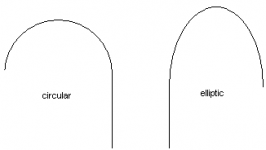
You might also want to try different shapes for the flare. I think they prefer elliptic vent flares over circular in industrial pipelines.
Someone used glass bottles to make flares on plastic pipes. Finding a >20cm diameter bottle could be difficult though.
You might also want to try different shapes for the flare. I think they prefer elliptic vent flares over circular in industrial pipelines.
Someone used glass bottles to make flares on plastic pipes. Finding a >20cm diameter bottle could be difficult though.
Attachments
I like the idea of heat bending PVC over a template of some sort. I'll have to try and come up with a way of making the template without a lathe. I'm going to have a go and will post some photos if I have any luck.
Ideas:
1. start with a few circles cut of MDF, attach to a sheet of mdf, the circles will just fit inside the vent, then you use some filler to create a "negative" onto which the PVC is pressed
2. cut circles out of 3mm MDF with increasing diameter, put them together so they form a stepped flare "negative" and use filler to smooth if you think necessary
There would need to be a measure for acceptable chuffing. I would suggest listening quite near the speaker to be able to say "yes it is chuffing" or "no it's" not. I think this is more accurate for testing than doing it from the seating position. Later a figure could be worked out for how much extra could be tolerated from the seating position
I would measure and show an SPL level. Then I would add comments on what level I think is acceptable. I think a mix of numbers and interpretation is needed. To be useful it has to not be room specific, hence I can't really do it from listening position as you say. Instead I could come up with some figures, then suggest a certain design will achieve -- db @ 1m. Then they can work out what it will be at their listening position based on distance, and I could suggest <-- db is a good target.
So I might conclude something like:
*example*
4" vent with 2" flare radius and 34m/s vent velocity >>> 46 db @ 1m so if you listen at 3m distance you will get approx 35 db, below the audible chuffing threshold of 40 db
*example*
I would have to talk about masking effect in some way too ...
In my case I should not need to underport to protect drivers. I can just use a signal below fb which causes large excursions and high vent velocity. My amp has 650w or can be configured to put out 2.4 kw if necessary. My drivers have 23mm one way xmax and 30mm xsus as well as very high power handling ~ 700w so pretty safe from a mechanical and thermal point of view, long duration of tones isn't required and it takes little power to reach xmax below fb where the cone is unloaded. With a rumble filter on and a signal above port tuning, it would take the kind of power that the driver can't handle long term thermally to even get close to xmax. I think my ears might complain before the drivers struggle!
Chuffmaster Paul,
Thanks for the idea of using filler for the template.
For our "chuff" tests it would be best to stick with a circular profile as that makes it easier to tease out the relationship between flare size and chuff level.
Later though, other shapes could be looked at such as Goodguys suggestion of elliptic cross section, and exponential flare profiles - any thoughts there?
I'll do a cheap and nasty first to determine how far the PVC is willing to stretch.
The testing method is starting to sound good - your amp amp drivers seem well capable.
One thing though, I would test at fb which gives us maximum vent velocity with minimum excursion.
Once you have it cranked up to the point of chuffing, and measure the SPL, that will be the result.
I cant see how you could separate the "tone from the chuff" - nor is it necessary to do so. From the measured SPL we calculate velocity and thats all we need.
Collo
Collo, I've seen someone use that vent flaring technique online, actually I just found it in my links:

and here is the site:
http://www.hilberink.nl/codehans/tannoy7.htm
I think the difference between flare profiles would be subtle, although I can see some benefit. As sound pressure moves out of the vent, there is inertia which restricts it from moving outward (normal to the length of the port). What you are trying to avoid is those nasty eddy currents that form when the fast moving wave moves past still air. Hence if you extend the flare out more along following the direction of the port, this gives the wave more chance to follow the profile around and "spread out" without separating. Very high velocity air has more inertia and tends to "shoot straight out" the port. This is the problem. If you can get the wave to exaxtly follow the flare profile there will be no eddy currents, no turbulence and if you can achieve this then the vent velocity is irrelevant. In practice there are limits.
The problem with elliptical flares is that they make the vent longer.
The vent dimples used by B&W are interesting. They are a clever way to change the aerodynamics such that the a air is in a sense pulled around the flare profile. I haven't been able to determine if my dimpled vents perform better, haven't gotten around to finishing them properly but I have two each of a 36 and 72mm flare which will be equal except for the dimples.
I showed that website to a friend who then went ahead and tried it out. He told me that you have to be careful with the heat gun, if you get heat too far down the pipe, it is weakened and will buckle.
In my previous example I used the point where I had simulated maximum velocity with the rumble filter. It was a bit below Fb. I used 15 Hz, Fb was 18 Hz.
Good point. With a fullrange SPL chart, it would be easy to separate 15 Hz tone vs chuffing which would be in the 200 - 2k range. With a simple SPL meter, the tone would be louder than the chuffing. To do it without an SPL/freq chart I would have to use a 4th order bandpass box, or actually see if I could get some real results out of speaker workshop! (would have to then make a preamp for my mic ... grrrr)
Actually another way to do it would be to have the sub outside, poking through a small hatch in the room and have MDF cut to seal it up but let the vent through. Then I'd need to get rid of the fan noise of my Behringer (another project I've put off!) since it is loud enough to be annoying in quiet parts of movies.
and here is the site:
http://www.hilberink.nl/codehans/tannoy7.htm
I think the difference between flare profiles would be subtle, although I can see some benefit. As sound pressure moves out of the vent, there is inertia which restricts it from moving outward (normal to the length of the port). What you are trying to avoid is those nasty eddy currents that form when the fast moving wave moves past still air. Hence if you extend the flare out more along following the direction of the port, this gives the wave more chance to follow the profile around and "spread out" without separating. Very high velocity air has more inertia and tends to "shoot straight out" the port. This is the problem. If you can get the wave to exaxtly follow the flare profile there will be no eddy currents, no turbulence and if you can achieve this then the vent velocity is irrelevant. In practice there are limits.
The problem with elliptical flares is that they make the vent longer.
The vent dimples used by B&W are interesting. They are a clever way to change the aerodynamics such that the a air is in a sense pulled around the flare profile. I haven't been able to determine if my dimpled vents perform better, haven't gotten around to finishing them properly but I have two each of a 36 and 72mm flare which will be equal except for the dimples.
I'll do a cheap and nasty first to determine how far the PVC is willing to stretch.
I showed that website to a friend who then went ahead and tried it out. He told me that you have to be careful with the heat gun, if you get heat too far down the pipe, it is weakened and will buckle.
One thing though, I would test at fb which gives us maximum vent velocity with minimum excursion.
In my previous example I used the point where I had simulated maximum velocity with the rumble filter. It was a bit below Fb. I used 15 Hz, Fb was 18 Hz.
I cant see how you could separate the "tone from the chuff" - nor is it necessary to do so. From the measured SPL we calculate velocity and thats all we need.
Good point. With a fullrange SPL chart, it would be easy to separate 15 Hz tone vs chuffing which would be in the 200 - 2k range. With a simple SPL meter, the tone would be louder than the chuffing. To do it without an SPL/freq chart I would have to use a 4th order bandpass box, or actually see if I could get some real results out of speaker workshop! (would have to then make a preamp for my mic ... grrrr)
Actually another way to do it would be to have the sub outside, poking through a small hatch in the room and have MDF cut to seal it up but let the vent through. Then I'd need to get rid of the fan noise of my Behringer (another project I've put off!) since it is loud enough to be annoying in quiet parts of movies.
I made flares for my small prototype box with routing the backplate with round edge router and then using heatgun like this
http://f5.infonet.ee/ergo/Rainbow/smaller%20box%20025.jpg
http://f5.infonet.ee/ergo/Rainbow/smaller%20box%20027.jpg
It looks a bit "home made" but for prototype when you have no place in your country selling the correct flared port it's OK I quess.
Ergo
BTW both ends are flared - first do the inner one and turn the pipe and do the second. Too many commercial design have it only half right as only the outer end is flared
Those pictures certainly show that using a heatgun to get a flare produces good results. The speaker from the Dutch site looks well made - was going to send him an email but couldn't find his address. He managed a 23 mm flare on a 100mm pipe. I have my doubts that I will be able to get a 70mm flare without going to a 2nd section made with some 150mm stock.
Ergo, your method uses the template on the outside of the port rather than the inside as the previous one did. From your photos, it looks like you had to use the socket to push the PVC into position. Did you get an even result? They look good fitted in the box!
Paul, the idea of putting the vent through to another room sounds OK but at or around fb, half of the sound is coming from the vent itself. This is why I always design for forward firing vents.
Maybe the Behringer would be better off outside! - do you use it for equalisation or just to tame room nodes? Is it any good? - the price certainly seems like a bargain.
I agree that working with PVC elbows is a nuisance. I always seem to wreck my knuckles trying to sand them smooth...
Collo said:Ergo, your method uses the template on the outside of the port rather than the inside as the previous one did. From your photos, it looks like you had to use the socket to push the PVC into position. Did you get an even result? They look good fitted in the box!
The result I got was quite good. I made 4 flares that I wasted to train myself before the final four were made. I got better with each flare and I assume that if I would have made 10 more practice pieces the result would have been near perfect.
It takes a bit experimenting to find a good temperature and air flow speed. So an adjustable heatgun is a big plus.
I'm sure that with a special mould inside the pipe would give better result but then again making such a mould would take considerable time. It has to be worth the effort either by quantity or other reasons.
Ergo
Collo,
There are 2 behringer units - I was referring to my Europower EP2500 amp which has a fan which is a bit noisy, as are all high power PA amp fans that I've heard.
My Behringer Ultracurve is another thing - it has no fan of course. I use it for a number of things. Primary use is fullrange eq, which includes room modes. I have it set up so that when my sub volume is set at a certain point, I get flat inroom response from 23 - 20k, I did not worry about getting down to 20 since the effect of a room mode and the rumble filter result in needing a lot of boost to get to 20 against settling for 23 Hz or so. It has other features such as dynamic eq to compensate for how the ear sensitivity changes with SPL (haven't really used that part much yet), stereo width controller (which I use), limiters (which I don't need for my subs as they have huge dynamics already), parametric eqs (which I use to make the top end a bit more natural sounding and sweet). It also has an SPL meter and RTA which gives a nice light show when "watching movies" lol ... The other night I was watching "resident evil: apocolypse" and noticed that they achieve an ominous heavy tense atmosphere by having in suspenseful moments very little treble, subdued midrange rising up to a peak in the bass which occurs sometimes at around 25 Hz rolling off sharply after, or other times at 20 Hz the bass is still rising up and goes off the Freq scale so I don't know where it starts to roll off.
The best thing about this unit is that it just makes everything work together. The tonal balance is more natural and neutral, it can easily remove boominess if it's there and if you momentarily disable it, the sound suddenly doesn't sound right. The only thing I don't like about it is that it sends a massive thump through my subs when I turn it off (even when the amp is off for less than 30 seconds). I have to turn down the passive attentuators on the amp every time.
Ahh, the Ultracurve! Here was me thinking you were referring to a simple BFD. Sounds like a sweet unit! 
The fibreglass would be good for a mass production situation, but for experimentation I think the heat gun method holds the most promise. I'm itching to have a go but I'm in the middle of building another sub and the weather here is lousy at the moment. I 'spose its worse in Melbourne eh!
A 70mm flare on a 100mm port would give an overall dia of 240mm - the same as a 10 inch driver. I think that would make an impressive combination. Definitely on the list.
Collo
Collo, yep this is no mere BFD I'm talkin' about here!
I suggest FG for a finished sub, would be tricky to do, but would make a nice diy project. At one stage I was contemplating making a whole subwoofer out of FG, but was put off by the cost. I'd like to do something in FG eventually though. Maybe small and simple, like some funky, sexy curvy gloss black computer speakers!
Yeah, except we also get this weather on a day that starts off sunny and warm! Most liveable city my foot!
It's on my to do list as well, when I finally do a seriously sexy sub box!
I suggest FG for a finished sub, would be tricky to do, but would make a nice diy project. At one stage I was contemplating making a whole subwoofer out of FG, but was put off by the cost.
I'd like to do something in FG eventually though. Maybe small and simple, like some funky, sexy curvy gloss black computer speakers! I 'spose its worse in Melbourne eh!
Yeah, except we also get this weather on a day that starts off sunny and warm!
Most liveable city my foot!A 70mm flare on a 100mm port would give an overall dia of 240mm - the same as a 10 inch driver. I think that would make an impressive combination. Definitely on the list.
It's on my to do list as well, when I finally do a seriously sexy sub box!
Attachments
I finally got a chance to try some flares.
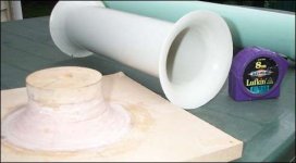
I used the same method as shown in the link Paul posted - A mold made from mdf rings of different sizes, covered with car body-filler and smothed with a circular scraper. The PVC pipe is heated and pushed onto the mold to form a flare.
My initial observations:
Using 90mm downpipe with a 2mm wall thickness, the best I could mange was a flare radius equivalent to 25mm.
The target was 36mm - the size the mold was designed for - but two factors limit how far you can go.
Firstly, the PVC will split at the outside edge. Taking care to evenly heat the edge can help a bit.
Secondly, the pipe will buckle futher up its length. This can be reduced by heating the pipe while it is actually on the former, but eventually the buckle happens.
After making a few test runs, I settled on an overall diameter for the flare of 140mm, which was achievable.
The next phase will be to produce a mold of 23mm so I can get a flare that will sit flat againts the box. Factoring in the wall thickness, this will mean the air will "see" a flare of 25mm.
Cleaning up the edge by 2mm with a circle jig will give a port mounting diameter of 136mm
After that, I will see how far 100mm sewer pipe (wall thickness 3.5mm) can be pushed.
Attachments
Interesting this mold idea. Actually I'm just trying a gray 160 mm nominal diameter, 153 mm inner diameter sewer pipe. And when I measured at the output of the port, I noticed that at this diameter size and 45 cm length, at 230 hz and above, the high frequencies suddenly start to come through the port quite unfiltered.
So, what if I would replace the single pipe with two smaller ones with equal total area. Of course the actual tuning would then remain the same, but would the high frequency 'hi pass' problem shift higher than the 230 hz what it is now?
So, what if I would replace the single pipe with two smaller ones with equal total area. Of course the actual tuning would then remain the same, but would the high frequency 'hi pass' problem shift higher than the 230 hz what it is now?
- Status
- This old topic is closed. If you want to reopen this topic, contact a moderator using the "Report Post" button.
- Home
- Loudspeakers
- Subwoofers
- Are multiple ports better ?