Arcam Alpha 8
Yes, you're right (somewhat sheepishly). I guess I was too eager to get it going to reread those posts and the parts took so long to arrive that I had forgotten about that light bulb precaution. So assuming that the bulb would have indicated there was still a problem, what should I have done? When I re-order the output transistors what other parts will I need?
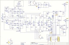
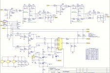
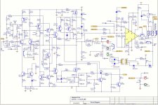
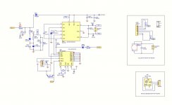
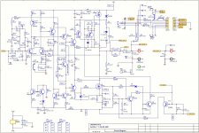
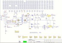
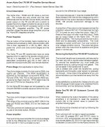
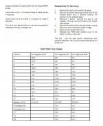
I have uploaded the service manual with circuit diagrams.
thanking you very much in advance,
older and a little more cautious.
Yes, you're right (somewhat sheepishly). I guess I was too eager to get it going to reread those posts and the parts took so long to arrive that I had forgotten about that light bulb precaution. So assuming that the bulb would have indicated there was still a problem, what should I have done? When I re-order the output transistors what other parts will I need?
I have uploaded the service manual with circuit diagrams.
thanking you very much in advance,
older and a little more cautious.
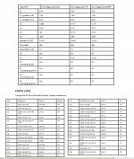
Arcam Alpha 8 service manual
The pdf file was too big for the system so I had to capture each page. But it will only let me upload 10 pages so I hope this is what is needed.
The pdf file was too big for the system so I had to capture each page. But it will only let me upload 10 pages so I hope this is what is needed.
Attachments
-
 Arcam Alpha 8 service manual (1).JPG176 KB · Views: 375
 -
 Arcam Alpha 8 service manual (2).JPG191.3 KB · Views: 373
 -
 Arcam Alpha 8 service manual (3).JPG176 KB · Views: 353
 -
 Arcam Alpha 8 service manual (4).JPG210.2 KB · Views: 346
 -
 Arcam Alpha 8 service manual (7).JPG89.7 KB · Views: 189
 -
 Arcam Alpha 8 service manual (6).JPG199.2 KB · Views: 267
 -
 Arcam Alpha 8 service manual (5).JPG221.8 KB · Views: 369
 -
 Arcam Alpha 8 service manual (8).JPG227.6 KB · Views: 158
 -
 Arcam Alpha 8 service manual (9).JPG115.1 KB · Views: 123
 -
 Arcam Alpha 8 service manual (10).JPG129 KB · Views: 136
OK... this will sound like a cop out but it's the quickest way to be sure.
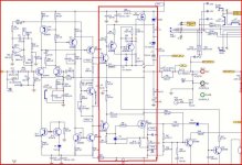
You need to check all the resistors in the red box having first removed all the transistors in that area.
Unsolder one end of D3 and D4 and check not short circuit. While still unsoldered check R7 and R8 as the diodes will effect in circuit readings. Make sure R1 and R1a read around 0.1ohms (they are in parallel). The other resistors should read OK in circuit if the transistors are removed.
Unless you are 100% confident in testing and measuring transistors replace all those in the red box. Goes without saying, but be certain you get the correct polarities in the correct locations. The type isn't very critical as long as the voltage rating is OK. Looks as though it will run OK for test without Q14 being fitted, so that just leaves 3 transistors and the FET's.
For initial switch on I would have Q15 temporarily shorted with a link across C and E to give minimum quiescent current.
And use a bulb")
Edit... minimum quiescent current is given by the preset being on maximum resistance (so Q15 is fully on)... confusing if you take the instructions literally and thinking they refer to ohms value. Minimum resistance of pot gives max (destructive) current.
You need to check all the resistors in the red box having first removed all the transistors in that area.
Unsolder one end of D3 and D4 and check not short circuit. While still unsoldered check R7 and R8 as the diodes will effect in circuit readings. Make sure R1 and R1a read around 0.1ohms (they are in parallel). The other resistors should read OK in circuit if the transistors are removed.
Unless you are 100% confident in testing and measuring transistors replace all those in the red box. Goes without saying, but be certain you get the correct polarities in the correct locations. The type isn't very critical as long as the voltage rating is OK. Looks as though it will run OK for test without Q14 being fitted, so that just leaves 3 transistors and the FET's.
For initial switch on I would have Q15 temporarily shorted with a link across C and E to give minimum quiescent current.
And use a bulb
Edit... minimum quiescent current is given by the preset being on maximum resistance (so Q15 is fully on)... confusing if you take the instructions literally and thinking they refer to ohms value. Minimum resistance of pot gives max (destructive) current.
Attachments
Last edited:
Hi Mooly
Thank you very much for your help. I really appreciate you taking the time to look this over and lead me through the (attempted) repair. I have followed your instructions to the letter. I unsoldered one end of diodes 3 and 4. Neither shorted.
R7 and R8 470 ohms - OK.
R1 and R1A .1 ohms - OK
R12 and R9 470 ohms - OK
all other resistors in vicinity OK
R10 - 320 ohms - not OK.
I unsoldered R10 and checked it again. Now it reads 470 ohms as it should. Put it back in and it reads 320. Still with the diodes 3 and 4 out of circuit. Is this a problem?
Re the transistors that have been removed:
one IRF540 - one completely shorted
other IRF540 - center and left shorted
BC557 - center and left shorted
BC546 - center and left shorted
BC556 - center and left shorted
BC 556 - center and left shorted
I have a new never-installed BC546 that also has the center and left shorted so I assume this means the other transistors that have center and left shorted are ok? (probably a dumb question
thanking you again,
If I install all new parts and the bulb test shows there is still a problem, what should I do then?
The resistors sound OK. R10 was reading low because of R11,13 and 14 which appear in parallel with it. R11 should also read low in circuit and OK out if all other resistors in place. They all seem OK from your readings.
The transistors... if a new one reads short between any leads then somethings wrong. Are you 100% sure you are testing using a "diode" range on your meter. Using a very high ohms range instead will give incorrect results. The fact all yours read the same suggests a measurement error.
What meter have you got ? Make model ? Digital or analogue ?
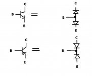
Scroll down here to bipolar transistors and look how the equivalent circuit really is two diodes. That is how (on a digital meter on diode check) they should measure. The PNP types are similar but imagine the diodes are reversed, so the readings are the opposite of the NPN type.
Testing semiconductors with analog and digital multimeters
Testing semiconductors with analog and digital multimeters
Analogue meters... well I'm as at home using an AVO8 as any DVM... in fact for semiconductor measurements on fairly "robust" stuff it's unbeatable.
Without seeing your meter I can only generalise but the first thing is that often the "polarity" of the test voltage is reversed compared to a DVM. If so everything you read in print for testing with a DVM will mean you have to reverse the leads or mentally make the switch.
The ranges offered by an analogue meter are critical to measuring transistors and diodes. You need a "low ohms" range... the range you would measure say a 10 ohm resistor on and be able to read its value accurately. That kind of range should allow basic tests showing the transistor junctions as conducting or not.
The beauty of the ancient AVO is it uses both a 1.5 and 15 volt battery for ohms ranges and so you can measure leaky junctions... but you have to be careful as 15 volts at the terminals can damage modern components even though the current is tiny. For your amp there are no worries, the semiconductor type are all tough in that regard.
Yes it does have two batteries. A 1.5 volt and a 9 volt. It is model 22-220.
here's a pic:
YoReparo - Multimetro Micronta modelo 22-220 - Instrumentos de Medición
here's a pic:
YoReparo - Multimetro Micronta modelo 22-220 - Instrumentos de Medición
Thanks for the link.
You are going to have to measure a known good device to see for yourself how it should read.
In general terms all NPN and all PNP devices read in the same way, ie a power transistor and a small signal one will give the same readings.
You can get free data sheets showing pinouts etc here, just type the device number (eg bc546) in the blank box.
Datasheet catalog for integrated circuits, diodes, triacs, and other semiconductors, view
Your BC546 transistor should read as follows. It's important to realise your meter is an unknown with regard to the polarity so if the following readings are "reversed" then your meter behaves like a more modern DVM with regard to polarity.
BC546... put your meter on the lowest ohms range and look at the data sheet for pinouts.
Middle leg (base) with black lead conected to it, and the red lead touched to either of the other two should read.
Reverse the leads and repeat and there should be no reading.
With the black lead on C and red on E there should be no reading.
With your meter now on highest ohms range... the one you measure millions of ohms on and the one that swings the meter right across just by gripping the probes test as follows.
Black on C and red on E and there should be no reading.
That's about as far as basic tests can go without knowledge of how to interpret other readings but should be good for 95% of testing.
The polarity I have given is based on "old" meters that give a positive test voltage on the negative meter lead on ohms ranges... yours may or may not be like this.
If you measure a diode (not a zener) on your meter out of circuit then you can apply that to the diagram below. Any other tests using high ohms range may give a reading due to the 9 volts causing the B-E junction to breakdown (not destructively) and read leaky. B-E junctions approximate and behave a little like 8 volt or so zeners.
Attachments
Merry Christmas Mooly
I just want to say again how much I appreciate this help you are giving me. Without it and you I'm sure this excellent amplifier would have to be relegated to the junk bin.
Now to the testing and results.
It is exactly as you described.
Test 1: The new unused BC546B with black on middle and red on either of the others reads 22 ohms at lowest ohms scale (although I don't know where the 0 adj should be). Test 2: Reverse leads and there is no reading.
Test 3: On highest ohms scale: black on C and red on E - no reading.
Using this same procedure to test the other transistors.
IRF 540 (one of pair - right channel)
Test 1: 0 ohms
Test 2: 12 ohms
Test 3: 0 ohms
conclusion: dead
IRF 540 (second of pair - right channel)
T1: black on pin2 red on pin3 = 2.5, black on pin2 red on pin1 = 28
T2: red on pin2 black on pin 3 = 2.3, red on pin2 black on pin1 = 0
T3: black on 1 and red on 3 - meter swings all the way to right
conclusion: dead
BC557
T1: 0 either way
T2: 18 both ways
T3: 0
conclusion: dead
BC 556B
T1: 0 either way
T2: reads
conclusion: dead
other BC556B
T1: 0 either way
T2: reads
conclusion: dead
BC546B
T1: 18 either way
T2: 0 either way
T3: 0
conclusion: OK
The following are the parts that I had replaced:
2 x BC 556B
1 x BC546B
2 x IRF540PBF
This time I will replace the following:
2 x IRF540PBF
2 x 556B
1 x 557B
Some questions:
Is it possible that the 557B was the original source of the problem?
I have a small collection of salvaged transistors, unfortunately none with exactly the same codes. Is it possible to substitute other ones? (now that you have given me a method to test them
If so, what are the most critical specifications that MUST be met?
best regards,
I would probably replace the mosfets, and shotgun replace Q3, Q4, Q5 and Q14. You should check Q15, and also check the trimpot RV1 and make sure it's not shorted - can sometimes happen.
Also make sure R13/R14 are ok as the output stage has gain and if these parts are dead, it could cause uncontrolled gain and oscillation that would blow the outputs.
Also make sure R13/R14 are ok as the output stage has gain and if these parts are dead, it could cause uncontrolled gain and oscillation that would blow the outputs.
Hi oncable,
First on substituting transistors... it has to be no for this. Although there are many many alternatives that can be used the chances of odd ones being suitable is remote.
You have to look at the basic ratings, voltage breakdown, current, gain, cutoff frequency, is it a device for rf use.... it goes on and on. Also any 2SC or 2SD 2SA 2SB numbers will all have different pin outs.
So pretty much as Jaycee says replacing those transistors. For what they cost fit new. I would definitely do as I sugested and initially short out Q15 C to E (The end pins) to ensure it runs at minimum current. And of course use the bulb. Make 100% you identify the devices correctly as fitting an NPN for a PNP will cause a failure.
The bulb will save the outputs failing if there is a problem.
Only when it appears OK remove the short from Q15 and with the bulb still fitted make sure the control works. As you turn the pot the bulb will light brighter... turn very slowly... if the bulb does increase in brightness turn the pot back again.
Reason is the rails will suddenly collapse due to the amp receiving less voltage and that can cause a lock up. If it did just switch off and reset pot back.
Happy New Year to Mooly and jaycee.
Now that the holidays are over I'm back to trying to get this amp fixed. In drawing up a parts list I thought I'd check good old Ebay and sure 'nuff, there is a supplier in Thailand that carries all the parts I need and way cheaper than the local one. My question now has to do with fuses. I need some 2.5 amp small glass fuses for the moment of truth when I try to fire it up. It would be simpler to get all parts from same source. Unfortunately that Thai supplier only has these:
PolySwitch Resettable Fuse Protection 72V 2.5A that look completely different but may be perfect for a dicey turn-on, given my track record Can I solder them to the old glass one and use them?
Now that the holidays are over I'm back to trying to get this amp fixed. In drawing up a parts list I thought I'd check good old Ebay and sure 'nuff, there is a supplier in Thailand that carries all the parts I need and way cheaper than the local one. My question now has to do with fuses. I need some 2.5 amp small glass fuses for the moment of truth when I try to fire it up. It would be simpler to get all parts from same source. Unfortunately that Thai supplier only has these:
PolySwitch Resettable Fuse Protection 72V 2.5A that look completely different but may be perfect for a dicey turn-on, given my track record
Can I solder them to the old glass one and use them?Happy new year.
Polyswitches aren't really suitable. They are slow, have high losses and have a very limited safe working voltage range.
Use the bulb tester as mentioned (no speaker load connected to amp). That will stop the outputs failing if there is a fault. Nothing can protect small signal stuff as even a few milliamps through a small transistor that has a high voltage across it will exceed it's ratings.
The positive aspect is that it's a simple circuit. If the components are OK and fitted correctly it will work.
Are you sure the ebay parts are reputable?
All the parts are available from RS-ONLINE.COM and are cheap.
The BC5..'s are only 4p each, OK you have to buy 10 at a time.
The IRF540's are about 80p each.
No worry about fakes from RS either - they'll be the genuine article.
While you are at RS also sell the fuses in boxes of 10.
The BC5..'s are only 4p each, OK you have to buy 10 at a time.
The IRF540's are about 80p each.
No worry about fakes from RS either - they'll be the genuine article.
While you are at RS also sell the fuses in boxes of 10.
Last edited:
contact the member X-pro, the developer of several creek models with only N-CH MOS-HEXFETs in the power output stage - go to post #8 aboutI have an Arcam Alpha 8 integrated amplifier that blows the fuse on powerup. I have checked it over and it seems the output transistors on one side have shorted. The problem is that i am struggling to find replacements.
There are 4 output transistors in total (2 per side) and they are as follows; On one side there are 2 x IRF540 MOROCCO W841 and on the other side there are 2 x IRF540 MOROCCO 3731.
I have had a look on the internet to find replacements but i can't find the specific IRF540 that i am after.
In the past i have had amp's that have had outputs that have gone and it has been easy to find replacement's specific to each channel (npn/pnp).
Any help would be very much appreciated.
http://www.diyaudio.com/forums/soli...50-mk2-circuit-descr-arround-q12a-wanted.html
because your Arcam amp uses similar topology in the power amp stage.
Mr. Alex Nikitin have great experience with this kind of topologies.
Last edited:
- Status
- This old topic is closed. If you want to reopen this topic, contact a moderator using the "Report Post" button.
- Home
- Amplifiers
- Solid State
- Arcam Alpha 8 DEAD