Dare you try it with speaker, just to make sure it is O.K. You might hear crossover distortion with no bias but thats fine. Then rig up the LED's and go through the set up again, don't leave it unattended keep watching that current. Another thought, the bulb is needed at first really, it can save problems, but it will drop the mains voltage a bit even if appears not lit, and when you put full mains back the current in the outputs will increase again. Just something to watch.
I intend to reserve a few hours to try to sit down and work through this as methodically as I can - the quick test may have pointed at the RV problem, but unfortunately not.
Let me make up that IEC cable with the light in series with it, and the LEDs... and away I can go with a bit more safety and ease.
Although I do still have one working speaker - a bit useless on it's own - until I can either find a replacement woofer or find someone else with a half-working pair!
You have certainly been most helpful and given me plenty of things to try to track this down.
One thing I do wonder; once the real problem has been identified and fixed, is it actually going to be worth replacing the likes of R40, Q8, etc. - the ones which have gotten too hot - to avoid problems when they decide to give up the ghost?
Also, I presume it's probably worth replacing thesame components in the right channel as I fix on the left channel, to (a) balance out the two channels, and (b) because the right channel component will almost certainly start to show the same symptoms within a few months or so?
I must say i did wonder what Arcam were smoking when they came out with a design with no VBE multiplier!! Especially with those tiny heatsinks in the revised Alpha. The circuit looks like a slight re-hash of the very popular A&R Cambridge A60 amplifier they released - but that had a much bigger heatsink.
Which issue circuit is yours?
edit: from what I've read, this circuit does actually have some thermal compensation, but in an unusual fashion - it has Q7 mounted near the heatsink!
Which issue circuit is yours?
edit: from what I've read, this circuit does actually have some thermal compensation, but in an unusual fashion - it has Q7 mounted near the heatsink!
It's the latest issue 9 board.
And yes, there is a transistor mounted near the heatsinks. Took a while to spot that one when testing the voltage drops across B/E. It's Q6, though - not Q7.
If you take a close look at the photo I posted earlier - Q6 (and Q106) are the little black transistors to the left of the left heatsink and to the right of the right heatsink.
Q7 and Q107 are the flat grey transistors Q7 on the left/middle and Q107 on the right near the transformer.
OK... I was actually thinking Q6 but the result is largely the same... the thermal tracking controls Q7's current sink, the standing current through the VAS and thereby controls the output bias. Not the way I'd choose to do it, but better than nothing!
One thing that springs to mind here is that this amp has VI limiting, so a fault in the biasing that would cause both outputs to turn on full would end up with the VI limiter pulling the bases of both drivers down and stopping this (although it'd probably blow a fuse and the VI transistors in doing so). I'd therefore be inclined to pull and test the outputs *and* the drivers, and also the VI limiting transistors (Q9 and Q10).
If those FST drivers are duff, the replacement is ZTX653/753 as far as I remember. Rapid Online stock them (codes 81-0226 and 81-0238). It might be worth replacing the bias pots too especially if they show signs of being unreliable. Rapid have the exact part Arcam used too by the look of it - code 67-0215.
All of the transistors in this unit are really cheap, so it may be worth replacing them anyway. My personal bet is that Q12 is suspect and should be replaced. If you replace the drivers, replace both of them - as the drivers are so cheap, i'd recommend replacing them in both channels as the ZTX devices are superior to the FSTs
Hi Jaycee,
It's sure turned into a long thread in a short time has this one. My gut feeling is still an intermitant O/C driver, I would put the money on Q11") as favourite. Q8 an outsider. It's nice to find a fault like this by measurement, you know then it's 100% fixed.
as favourite. Q8 an outsider. It's nice to find a fault like this by measurement, you know then it's 100% fixed.
I had some further thought on this, and I will post them after this. I was hoping that we could get a reading such as -37 output and +35 say collector Q7. I missed those TO92's up against the heatsink in the picture, when I saw the circuit I nearly did a "Victor Meldrew" I don't believe it
I'll post the other reply to wprice now.
Cheers Karl.
It's sure turned into a long thread in a short time has this one. My gut feeling is still an intermitant O/C driver, I would put the money on Q11
as favourite. Q8 an outsider. It's nice to find a fault like this by measurement, you know then it's 100% fixed.I had some further thought on this, and I will post them after this. I was hoping that we could get a reading such as -37 output and +35 say collector Q7. I missed those TO92's up against the heatsink in the picture, when I saw the circuit I nearly did a "Victor Meldrew" I don't believe it
I'll post the other reply to wprice now.
Cheers Karl.
I went to give the amp a checking over (checking the voltages as per Mooly's suggestions) last night, but it's now 0V across the output speaker terminals (fuse is till OK and nothing plugged in).
I still haven't got the bits for the bridge rectifier, etc. to test this properly and am hoping to pick them up over the weekend or on Monday so that I can have a good bash at it.
I still haven't got the bits for the bridge rectifier, etc. to test this properly and am hoping to pick them up over the weekend or on Monday so that I can have a good bash at it.
Further thought's, but first, are you O.K. unsoldering components using braid ? Don't try and wiggle them out while heating. And pull the plug out as well. Earthed amp, earthed iron, charged up caps-BANG  or unnoticed damage to a transistor
Right, we know the quiescent current set by RV1 was much to high- 90mv I think you said across RV41/2. Now we don't know for sure if this is the only problem, it may or may not be ! Setting RV1 on minimum should allow the outputs to run cold. The LED's will show if a fault still occurrs, and, if it does, it seems the setting of RV1 while incorrect was a red herring. The outputs should stay cold even under fault condition provided no load is connected. Did you swap the FET, if you have you need two sets of LED monitors, one on each channel. Cheapskate method follows , one monitor between both positive speaker outputs (remember to replace fuse). This will show fault has occured but not on which channel.
To help show up the fault can you heat the PCB with a hairdryer while it is on and see if this causes fault, in particular those transistors I mentioned. If you can get it in it's faulty state measure and note voltages on Q7 and Q8 collectors, then measure base/ emmiter volt drops on those drivers first, then others. Any over 0.7/8 ish are faulty.
or unnoticed damage to a transistor Right, we know the quiescent current set by RV1 was much to high- 90mv I think you said across RV41/2. Now we don't know for sure if this is the only problem, it may or may not be ! Setting RV1 on minimum should allow the outputs to run cold. The LED's will show if a fault still occurrs, and, if it does, it seems the setting of RV1 while incorrect was a red herring. The outputs should stay cold even under fault condition provided no load is connected. Did you swap the FET, if you have you need two sets of LED monitors, one on each channel. Cheapskate method follows
, one monitor between both positive speaker outputs (remember to replace fuse). This will show fault has occured but not on which channel. To help show up the fault can you heat the PCB with a hairdryer while it is on and see if this causes fault, in particular those transistors I mentioned. If you can get it in it's faulty state measure and note voltages on Q7 and Q8 collectors, then measure base/ emmiter volt drops on those drivers first, then others. Any over 0.7/8 ish are faulty.
I'm OK desoldering components - I have a solder sucker, though instead of braid.
Thanks for the suggestions - I understand what I need to try...
I didn't get round to swapping the FETs yet, nor trying your suggestion of temporarilly shorting the source and drain to see if the output remained at -37V - the output stubbornly went back to normal and started working, as per my previous messages.
As for a bridge reccy, I was just going to stick four 1N9001 (I think that's the number off the top of my head) diodes together - that should be pretty cheap!
Leave the FET then, let's try and be sure and get it in it's faulty state. Any diodes OK (IN4001) , a separate bridge is less messy to wire up . Worth trying braid, you need a good hot iron with a decent sized poker on the end (it's much easier working with a large bit on stuff like this) and well tinned, just lay braid over component, and apply iron, the solder will instantly flow to the braid and the part will lift cleanly out. Million time better than a sucker.
And try the hairdryer, it's a recognised technique, it works.
. Worth trying braid, you need a good hot iron with a decent sized poker on the end (it's much easier working with a large bit on stuff like this) and well tinned, just lay braid over component, and apply iron, the solder will instantly flow to the braid and the part will lift cleanly out. Million time better than a sucker.And try the hairdryer, it's a recognised technique, it works.
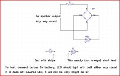
Thanks for that. That's pretty much what I thought, although I would have put the resistor on the other side of the bridge. Makes more sense where you have it though, to limit the current through the bridge itself.
And yes, a 9V battery directly to an LED isn't a great idea. A typical LED is 3V or 5V max operating voltage usually, as far as I remember.
Never used braid before - I always imagined it would be worse since it would kind of share the solder with the board - rather than sucking it away. I'll pick some up at Maplin when I get the other bits...
Ah yes.. 1N4001 is the number I was thinking of.
I will definately keep you updated - in the worst case, I'll be asking for more suggestions as to what to check next!!!
I currently need to go get bits that I thought I already had spare (i.e. LEDs, diodes) before continuing... but it's not beaten me yet. It won a battle by taking out a speaker, but it's not won the war yet!!!
I currently need to go get bits that I thought I already had spare (i.e. LEDs, diodes) before continuing... but it's not beaten me yet. It won a battle by taking out a speaker, but it's not won the war yet!!!
Mooly, nice idea with the hairdryer! im going to try that one out next chance i get. a similar technique that i sometimes use w/ intermittent faults is i test for the presence of the fault (in this case, -37V at the speaker terminals) while i tap on and/or wiggle suspect components. if the problem appears (or disappears) when doing this, you've found the area of the problem. doesn't always work of course, but ive been surprised by how many times it actually does.
regards and good luck!
regards and good luck!
Had some time to play with this this evening...
Wired up the 60W lamp again, switched amp on, tested speaker outputs. After a while, it went into the faulty state and measured -36.1V on the output. Great.
Left multimeter probes connected to the output - twiddled RV1 from max to min - not a jot of difference. Still -36.1V on the output.
Measured the voltage on the collector of Q7 and Q8, which was -37.1V (yes, slightly lower than the output on the speaker - I double-checked that).
Haven't got the b/e voltage drops again yet - the amp has reverted to it's non-faulty state before I got to testing those. Had the hairdryer on it, but no luck yet - it hasn't reverted to the faulty state yet.
Don't forget you have a working channel. Measure everything on the working channel and write it down. Then when you next get the faulty channel, check everything. Any major differences point to the suspect area.
You mainly want to measure around the transistors. I'm guessing this is a faulty driver myself - it might simply be worth ordering the new parts and putting them in. You won't lose much by doing so.
You mainly want to measure around the transistors. I'm guessing this is a faulty driver myself - it might simply be worth ordering the new parts and putting them in. You won't lose much by doing so.
- Status
- This old topic is closed. If you want to reopen this topic, contact a moderator using the "Report Post" button.
- Home
- Amplifiers
- Solid State
- Arcam Alpha 3 Left Channel broken...