My multimeter actually has a transistor test option on it, so that would narrow things down somewhat (as a backup to the datasheets), although I'm still intrugued as to Mooly's foolproof test...
I've already noted the various replacements as mentioned eralier in the thread... thanks.
I've already noted the various replacements as mentioned eralier in the thread... thanks.
This is going to be a bit of an anti-climax I think. I tend to take nothing on trust, and it's nice to be able to identify an unknown part connection wise. Data sheets are fine 95% of the time, but I have come across replacement parts with different pin outs to the originals on rare occasions (still the same type no).
So, meters first, I take it it's a digital meter your using. You know, you just can't beat an AVO 8 for checking transistors, the 15 volt battery showed up leaky parts that DVM's fail to show. Back to the DVM, when you put it on diode test, the meter lets a small current flow through the test leads and the meter actually shows the volt drop across the meter leads which in this case is the semiconductor junction you are measuring. So you measure a diode and it show 645, thats 645 mv, about right for a silicon junction, with the leads reversed the reading will be whatever that particular meter happens to show with nothing connected to the test leads. Mine shows 3154 which just means the voltage at the probes is 3.154 volts. The red lead is also the "positve" potential of the test current. (AVO's and many other analogue meters are the reverse).
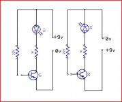
So we have a 3 legged thing on the bench which we need to identify. With our meter on diode test we need to find the leg that, when we connect one of our meter leads to it, it reads as a diode (the 650mv drop) to each of the others. If the "common" lead is the red one it is an N.P.N if the black is the common, it is P.N.P. and this commom connection is the Base. So far so good, but how do you identify the emmiter and collector ? A PP3, a couple of resistors and an LED is as good as anything, and if the transistor were slightly leakey it shows up.
So here it is, the LED is unlit until you touch the 22k resistor to the base. If the device is leakey the LED will glow with no base current. Note the polarity of the battery and LED for PNP.
So, meters first, I take it it's a digital meter your using. You know, you just can't beat an AVO 8 for checking transistors, the 15 volt battery showed up leaky parts that DVM's fail to show. Back to the DVM, when you put it on diode test, the meter lets a small current flow through the test leads and the meter actually shows the volt drop across the meter leads which in this case is the semiconductor junction you are measuring. So you measure a diode and it show 645, thats 645 mv, about right for a silicon junction, with the leads reversed the reading will be whatever that particular meter happens to show with nothing connected to the test leads. Mine shows 3154 which just means the voltage at the probes is 3.154 volts. The red lead is also the "positve" potential of the test current. (AVO's and many other analogue meters are the reverse).
So we have a 3 legged thing on the bench which we need to identify. With our meter on diode test we need to find the leg that, when we connect one of our meter leads to it, it reads as a diode (the 650mv drop) to each of the others. If the "common" lead is the red one it is an N.P.N if the black is the common, it is P.N.P. and this commom connection is the Base. So far so good, but how do you identify the emmiter and collector ? A PP3, a couple of resistors and an LED is as good as anything, and if the transistor were slightly leakey it shows up.
So here it is, the LED is unlit until you touch the 22k resistor to the base. If the device is leakey the LED will glow with no base current. Note the polarity of the battery and LED for PNP.
Attachments
wprice99 said:
it's taken out the crappy speaker ripped from an old tranny radio (I know that due to the accompanying smoke coming from it!)
for testing, perhaps hook a cap (say 470uF 63V) in series between the amp pos. output terminal and the speaker. granted not ideal for sound quality, but this should protect your test speaker from the dangerous dc offset when the fault occurs.
That does look like a pretty simple test for the transistors, Mooly - probably slightly more complex than I first imagined, but still pretty simple.
Gain... yes a capacitor probably would have protected the speaker somewhat, but I really didn't care about it. When I was a kid, I used to take old broken record players, radios, etc. apart for the bits - which I could re-use in small circuits. It just happened to be one of those bits I still had kicking around, so I really wasn't in the slightest bit bothered about it. Trust me when I say the capacitor would have made no difference to the sound quality!!!") In fact, in the same box of bits, I might even have another small(er) speaker, so I might actually try that to see if I can get the fault to reappear while I'm waiting for replacement components.
In fact, in the same box of bits, I might even have another small(er) speaker, so I might actually try that to see if I can get the fault to reappear while I'm waiting for replacement components.
Speaking of replacement components, I ended up getting them from Farnell. Not quite as cheap as RapidOnline, and similarly priced to CPC (pretty much the same company, I believe), but they did have all bits in stock (ZTX replacements for FST's, but the rest are the same parts - the MPSA56 was the one which seemed to be hard to find - which is Q8!). Also ordered some OPA2604's and TL072's to have a play with once the amp is back working properly again.
Gain... yes a capacitor probably would have protected the speaker somewhat, but I really didn't care about it. When I was a kid, I used to take old broken record players, radios, etc. apart for the bits - which I could re-use in small circuits. It just happened to be one of those bits I still had kicking around, so I really wasn't in the slightest bit bothered about it. Trust me when I say the capacitor would have made no difference to the sound quality!!!
In fact, in the same box of bits, I might even have another small(er) speaker, so I might actually try that to see if I can get the fault to reappear while I'm waiting for replacement components.Speaking of replacement components, I ended up getting them from Farnell. Not quite as cheap as RapidOnline, and similarly priced to CPC (pretty much the same company, I believe), but they did have all bits in stock (ZTX replacements for FST's, but the rest are the same parts - the MPSA56 was the one which seemed to be hard to find - which is Q8!). Also ordered some OPA2604's and TL072's to have a play with once the amp is back working properly again.
Good to here you have ordered the bits, just the small signal or are you getting the outputs as well ?
Using a cap to prevent damage as Gain suggests is a good idea, just remember that a fault can swing the output either way (yours we know which way - negative), so really you need a bipolar cap or, return the speaker to the negative rail and then the cap can never get reverse biased.
Let us know when the bit's come and remember to set the quiescent current back at zero to begin with and readjust it a bit at a time. It says on the circuit to adjust after 30 mins of delivering 3.5 RMS into 8 ohm. Thats about 1.5 watts RMS, does not sound much, but it's a "fairly loud" listening level.
And if it does not work after all this,
 , but it will
Using a cap to prevent damage as Gain suggests is a good idea, just remember that a fault can swing the output either way (yours we know which way - negative), so really you need a bipolar cap or
, return the speaker to the negative rail and then the cap can never get reverse biased. Let us know when the bit's come and remember to set the quiescent current back at zero to begin with and readjust it a bit at a time. It says on the circuit to adjust after 30 mins of delivering 3.5 RMS into 8 ohm. Thats about 1.5 watts RMS, does not sound much, but it's a "fairly loud" listening level.
And if it does not work after all this,
, but it will Hi Mooly,
I've ordered everything from Q2-Q12 (and Q102-Q112 for the other channel); I've left Q13 and Q14 for now. Ideally I'd still really like to get it into the faulty state again, and do some more measurements to confirm that it really is Q8 gone. But the fact that when I touched the probe onto either base or emitter of Q8 caused the LED to dim down to 0V (it wasn't an immediate reversion, but took about 1 sec for the LED to go off) seems pretty indicative that that's the part.
And I've ordered replacements for RV1 and RV101 too.
An update...
Parts have now arrived, but this week has just been so busy with work that I haven't been able to do anything to it yet, including taking out Q8.
Have had the amp on, in the kitchen, wired up to an even worse speaker (with a capacitor as suggested by gain), and it very randomly and very occasionally enters the fault state and back again, with the obvious audible crack and the LED lights up. Probably happened about twice in the last couple of days, so it's pretty random.
I caught it in the faulty state, and the voltage drop across R27 appears to be zero, so it seems that the base of Q8 isn't on.
However, as soon as i touched the probe on Q2 collector (I avoided Q8 base due to suspected cooling from the probe), the amp has now switched back to working again. It didn't switch back after a while - it was instant, as soon as the probe touched the leg.
Presumably, the (minimal) current passing through the multimeter has changed the current flowing in the circuit and disrupted whatever is faulty, causing the voltages somewhere to change enough for it to go back to the working state.
I'm not not so sure that Q8 is the problem...
Mooly? Any words of wisdom (apart from 'change everything and done with!')?
Hi, wondered where you'd got to .
Still Q8 ! It's favourite in my book. Why not change just Q8 and see what happens, failing that change Q11. It's a toughy with it being so intermitant, and if you can't get to read the voltages when it is faulty, it's very very difficult. You have to think "what will cause these fault conditions" and the probability is those drivers, they run hot, and most unscientific of all, they are just that type that does this sort of thing. Could it be a resistor, very very unlikely, and you are sure and we have been over this many times, there are no dry joints anywhere. So a capacitor then, unlikely, c18 going leaky/short might give these symptoms but the type shown, polypropolyne, polystyrene, they don't often give trouble. Ceramics yes.
You have to remember when you touch anything with your meter the probe could have many 10's of volts on it, like static, and this could easily "shock", that's not the right word is it, the faulty component particularly.
So you are still on track for a result here hopefully, oh yes, and watch the polarity of the cap your using, you need it wrong way round for your fault.
Regards Karl
wow that is really bazaar about the multimeter. is the meter you are using a digital or one of the older analog types? supposedly the analog meters had lower input impedances than the digital ones (although its hard to imagine a situation where the impedance of either type of meter would have any sizable impact on the type of circuit you are testing)
you are absolutely certain you were set for measuring voltage and not accidentally resistance? because in the latter case you would be applying voltage to the circuit which would certainly affect it.
you are absolutely certain you were set for measuring voltage and not accidentally resistance? because in the latter case you would be applying voltage to the circuit which would certainly affect it.
Definately on voltage... and it's a digital multimeter.
I know it's easy to sometimes overlook the obvious, but in this case, I can 100% guarantee that it was on voltage
I've dug out some test leads with croc clips on either end, and these have been sitting on various points where I want to get the voltage (being very careful that they aren't touching anything else) to try to eliminate any heat-related issues with the probe, but even that's not helping.
Well, Mooly... looks like Q8 is broken...
Had the test leads on various bits (to avoid 'shocking' the amp when probing voltages) and managed to get these voltages out when in the faulty state:
Voltage drop across R27: 0V
Q8 emitter voltage: +38.9V
Q8 base voltage: +35.9V
Bit of chance, really, but I noticed that the left channel does a funny thing with the LED when switching the amp on, but only if it's been off for a few seconds (i.e. C211 and C210 have discharged, and the +37/-37V rails are lower then 5 or 6 volts. When I switch it on, the LED glows in a kind of decaying sine wave - at most I saw two glows, but normally only one. That was definately different to the right channel.
Anyway, while switching it off and back on again several times (I figured that if this behaviour was consistent, then I'd be able to replace Q8, and see if it did the same to know if I'd fixed it). But anyway, it hit the fault state again, and I was armed and ready with the probes already connected.
So the Q8 base is lower than Q8 emitter, but no current flowing through R27. Presumably, this actually sounds like Q8 base is a bit screwy, otherwise there's be some current flowing through emitter->base?
Once I get a half-hour later today (or the weekend), I'll swap out Q8 and see what it does...
Good 3 volts DC across a forward biased junction, not possible, so it's looking good.
A decaying sine wave, is that another technical term It's very accurate actually. What you are probably seeing is the action of the DC servo as it settles and a small offset appears at the output. This is what gives that "switch on thump". It's normal, some designs have a speaker relay that allows this to settle before connecting the speakers.
3 volts DC across a forward biased junction, not possible, so it's looking good. A decaying sine wave, is that another technical term
It's very accurate actually. What you are probably seeing is the action of the DC servo as it settles and a small offset appears at the output. This is what gives that "switch on thump". It's normal, some designs have a speaker relay that allows this to settle before connecting the speakers.Regarding the decaying sine wave, it seemed strange that this is only visible via the LED on the left channel; the right channel appears nicely off during switch on. Wasn't sure if it may have been related. Hence why I was checking to see if it was consistent.
I'll let you all know once I've replaced Q8 (I'll actually replace all the transistors anyway, but I'd like to give it some testing after replacing just Q8).
I'll let you all know once I've replaced Q8 (I'll actually replace all the transistors anyway, but I'd like to give it some testing after replacing just Q8).
Can't answer that really. I think we have to fix this fault first before seeing if there is anything else going on as caps charge etc. All amps generate an offset of some sort at switch on, some much worse than others. Your circuit shows some component changes to try and improve on this. That zener D5 for example, has been but there to allow the negative rail to rise to around -6 volts before the BD139 begins to conduct.
There will probably have been "complaints" of switch on thump and Arcam have tried to fiddle the issue, I say fiddle because the answer is to provide both switch on delay and DC offset protection, but it all adds to the cost.
You need a 'scope to look at the output and see what is causing it, but I am sure there won't be a problem, it will be normal.
Do you mean like the 'leftover screw' syndrome... whenever you take something apart, there's always either a screw leftover, or (possibly worse) a screw short which could be floating around the case!!!
Yes, I'll be doing things one bit at a time - take Q8 out - stick replacement back in. Just to make sure nothing's left out. At the moment, nothing has been removed; the original lamp soldered across the fuse has been removed, and I made up an IEC cable with the lamp in series with it instead; other than that, it's just been croc-clips and test probes (and stuff like bridge/LEDs on the actual speaker outputs, so I definately won't miss removing those!).
And you're probably right about the 'complaints', I suspect. The service manual does say that the issue 9 board (which is mine) has 'switch off thump reduction' added to it. That and Q1 for switch-on mute in the circuit.
- Status
- This old topic is closed. If you want to reopen this topic, contact a moderator using the "Report Post" button.
- Home
- Amplifiers
- Solid State
- Arcam Alpha 3 Left Channel broken...