Hi Shin,
Sorry if it's OT but I just want to ask you the software version of your Mach3, are you using 3.43.66? or 3.43.62?
I'm using 3.42.40. Its been 100% stable for me and Mach can be funny so if it ain't broke I don't update it.
Nice!
'tis a lot of dust though, no?
I still think the better idea is a continuous stream(s) of compressed air at the bit/work area scattering the debris to the edges of the work surface (..with a vacuum pick-up from there). And though speculative, I'd still imagine that compressed air streams would cool the bit (a "bit") and prolong bit-life. (..again, similar to what heavy industry machines use with liquid for metal milling.)
My understanding is that the chips created by the cutter actually take away a fair bit of heat (which is why you want to create chips rather than dust). However, I have seen compressed air used to clear debris and cool a cutter - especially for hobbist metal mills where liquid jets aren't practical.
Ant - superb work. Though there are some movements (e.g. around the 30-40s mark) that look a little slow for the cutting rpm and would risk heat problems.
Cheers mate.
That's the ramping moves I think your talking about. I've started playing around with helical and angular Z entry and it works a bit differently to straight plunging. I didn't realise that these are vector based and so you have to set your feed rate higher to get the speed as if you were straight up plunging. That wasn't what burned the cutters though. I'll explain more about that later in this post!
That 105mm cutter is a monster. I'll bet the deflection problems were interesting.
Yup. In my initial set of toolpaths I naively thought using the long cutting to get through the whole material was a great idea - save time changing bits, keeps the code simple and smaller. Wrong! You really only wanted to be doing the bare minimum with those massive cutters, just the parts where only they can reach. Anything else, use something smaller! In the end I broke it up into three tool lengths, one at 40mm another at 75mm and the 105mm. That worked but for the profile around each part there simply wasn't enough room to clear the chips when that valley got deep and it start burning cutters within minutes due to massive rubbing and recutting of chips. In the end I had to flip the part over and come at it with the 40mm cutter from both sides leaving only 20mm right in the middle for the long cutter to get at.
In hindsight there would be a couple of things I'd do differently. The most important being to size the stock to just over the size of the part and that'd do away with the deep profile problem I had. I didn't have the most optimised g-code ever either and was running back and forth between the PC making iterations to the code whilst cutting.
Like the idea of having a couple of baffles along the length of the machine so the chips are kept on the table, rather than falling onto the rails.
Yeah that was pretty much mandatory as you can see! Keeps everything but the finest stuff that floats down in the air and finds their way on to them.
BTW Scare me - how long did that whole job take?
Its not good!
Rear side took the longest and that's simply because that was the side I did first and bumped into all the problems there. By the time I'd flipped it over onto the front I'd got it figured out and things went like clockwork.
So for the rear side it was an entire day but only a couple of those hours were spent cutting. The rest was head scratching and making changes. The front side was 6 hours from start to finish including tool changes and pausing the machine occasionally to vacuum the chips.
If I did it again I think I could have it done within 8 hours quite easily, probably less because I was on the conservative side with speeds. I'll be doing some more two sided parts in the future such as wave guides but I want to make a permanent jig setup for those as its something I need to be able to do over and over rather than just a one off like these.
My understanding is that the chips created by the cutter actually take away a fair bit of heat (which is why you want to create chips rather than dust). However, I have seen compressed air used to clear debris and cool a cutter - especially for hobbist metal mills where liquid jets aren't practical.
Yeah, it's just a guess on my part.

I've not heard of debris sinking heat before.. seems strange to me.
 I tend to think of it causing added friction (with resulting heat) where it might contact during a pass-through or cause dust to pile-up during cutting.
 Wow! Will you then pour silicone on that to make the moulds? Thanks for the links btw! I will receive my "kit" tomorrow hopefully, then i will start to experiment with fillers, marble powder and metal powders! I't would be pretty badass to have a brass like baffle!
Yep that's pretty much the rub of it. Have fun with it and be sure to do some test moulds first to get the hang of it. Its trickier than the damned utube video's I've watched countless times make out!
..but only a couple of those hours were spent cutting. The rest was head scratching and making changes. The front side was 6 hours from start to finish including tool changes and pausing the machine occasionally to vacuum the chips..
That seems pretty fast to me.
I also really liked the smooth "round over" cutting on the baffle side-edges - very slick!
Yeah, it's just a guess on my part.
I've not heard of debris sinking heat before.. seems strange to me.
It does happen. The flutes on the cutter heat as they slice away a chip out of material but because the chip is in full contact with the knife on the flute then some of that heat is transferred into it.
The effect is at its best in metals since they have a much higher thermal conductivity than wood and plastics etc. But I can attest that when you have you have your speed and rpm set correctly in wood and your making chips and not dust then if you pick up freshly cut chips they're warm.
Last edited:
I'm using 3.42.40. Its been 100% stable for me and Mach can be funny so if it ain't broke I don't update it.
The reason why I ask is beacause the Mach3 2010 screenshot tool changer doesn't work on some other version of Mach3. Thanks for your reply.
Here's the pics.
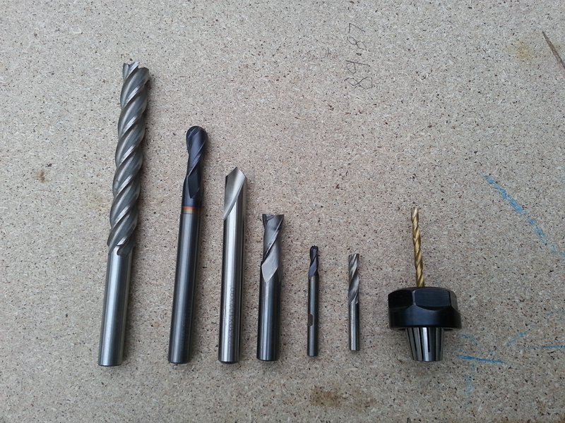
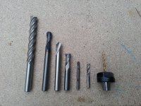
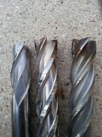
Cutters used for this job
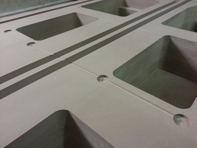
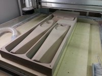
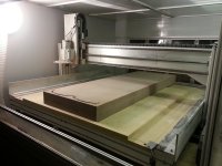
Levelling the sacrificial board flat and cutting reference edges and dowel holes used when flipping the block over.
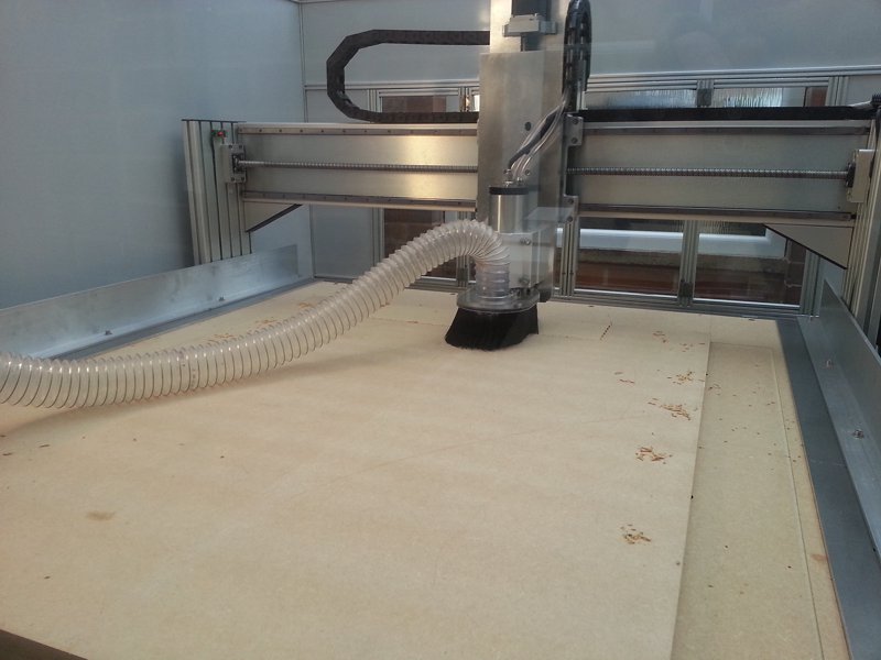
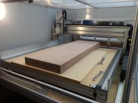
Modelling board in place. Not easy picking this up by yourself!

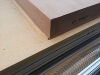
Reference edges used for alignment(parallel to the X and Y axis)

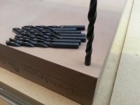
I bought a pack of cheap drill bits, used one of them to cut the dowel holes and then cut the rest down to serve as the dowels.

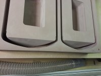
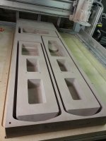
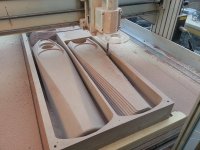
Rear side complete.
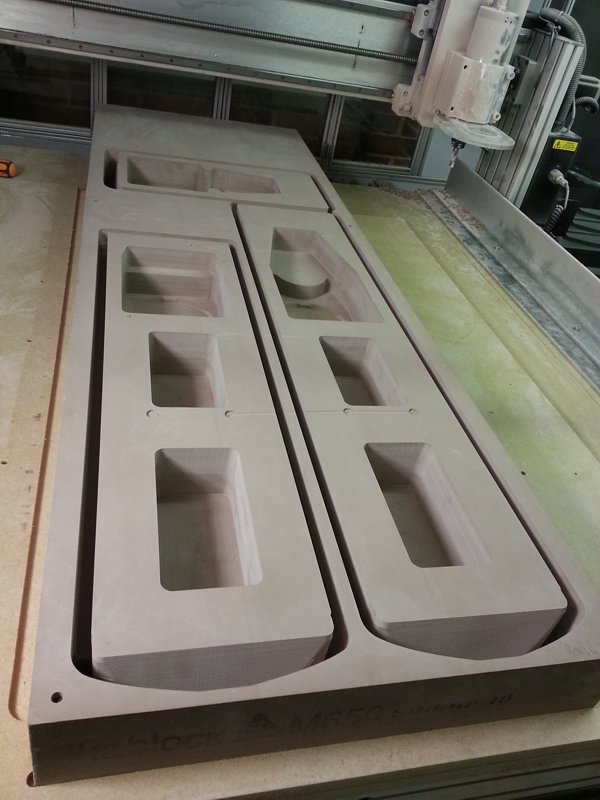
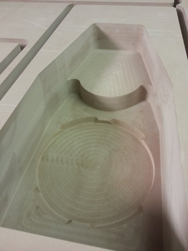
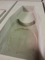
Shot showing the bottom of the baffles from the rear
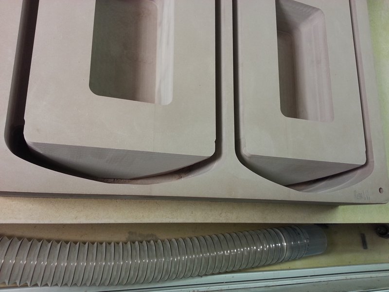
Rear of driver details
The only bit that didn't go to plan. I entered the clearance height wrong on a drilling operation. Luckily didn't snap my expensive drill bit! Did scar the baffles though but since these are used for the mould I can go ahead and fill/sand.
Cutters used for this job
Levelling the sacrificial board flat and cutting reference edges and dowel holes used when flipping the block over.
Modelling board in place. Not easy picking this up by yourself!
Reference edges used for alignment(parallel to the X and Y axis)
I bought a pack of cheap drill bits, used one of them to cut the dowel holes and then cut the rest down to serve as the dowels.
Rear side complete.
Shot showing the bottom of the baffles from the rear
Rear of driver details
The only bit that didn't go to plan. I entered the clearance height wrong on a drilling operation. Luckily didn't snap my expensive drill bit! Did scar the baffles though but since these are used for the mould I can go ahead and fill/sand.
Attachments
-
 Baffle Masters 02.jpg78 KB · Views: 838
 -
 Baffle Masters 09.jpg67.6 KB · Views: 810
 -
 Baffle Masters 08.jpg65.8 KB · Views: 810
 -
 Baffle Masters 07.jpg79 KB · Views: 808
 -
 Baffle Masters 06.jpg92.1 KB · Views: 810
 -
 Baffle Masters 05.jpg78.7 KB · Views: 818
 -
 Baffle Masters 04.jpg88.4 KB · Views: 822
 -
 Baffle Masters 03.jpg90.1 KB · Views: 813
 -
 Baffle Masters 01.jpg169.4 KB · Views: 809
Flipped over and ready to do the fronts

Machining the fronts

Front side complete

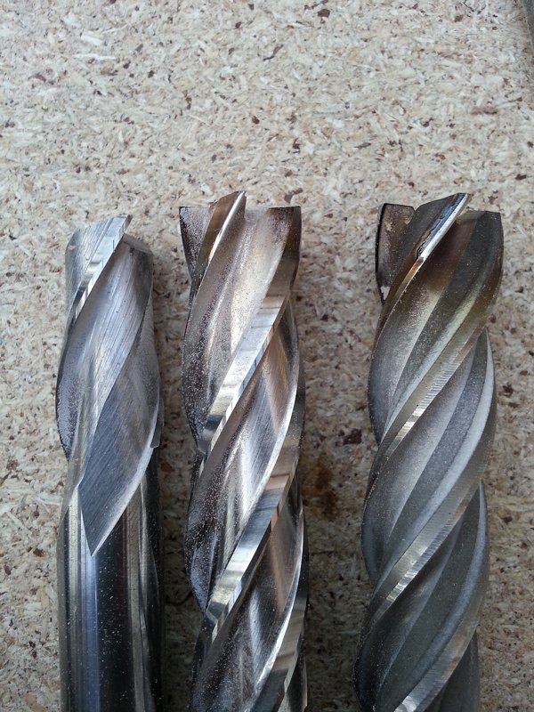
Here's a shot showing the superiority of carbide vs. highspeed steel. These stay sharp, don't blunt and overheat.
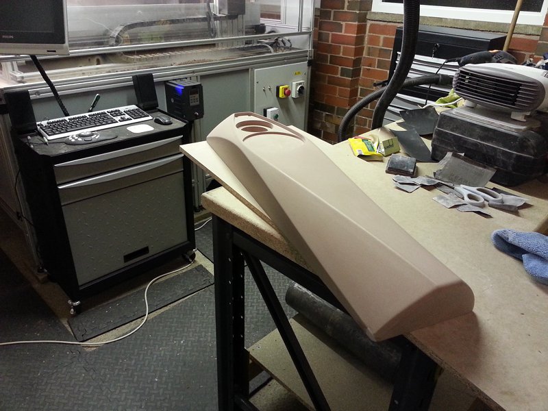
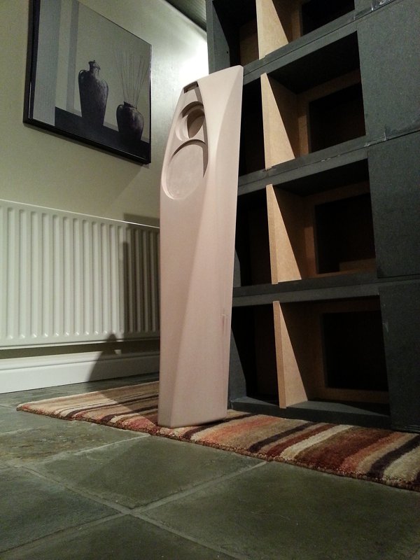
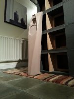
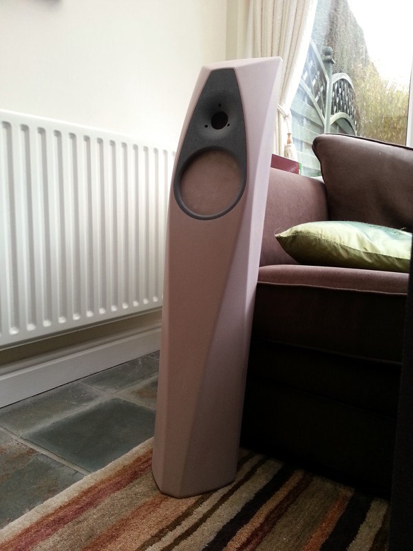
The finished article after some light sanding to remove tooling marks.
And against a stack of Apollo cabinets for scale
Machining the fronts
Front side complete
Here's a shot showing the superiority of carbide vs. highspeed steel. These stay sharp, don't blunt and overheat.
The finished article after some light sanding to remove tooling marks.
And against a stack of Apollo cabinets for scale
Attachments
-
 Baffle Masters 16.jpg91.6 KB · Views: 832
 -
 Baffle Masters 15.jpg99 KB · Views: 819
 -
 Baffle Masters 14.jpg119.8 KB · Views: 817
 -
 Baffle Masters 13.jpg150.5 KB · Views: 811
 -
 Baffle Masters 12.jpg92.7 KB · Views: 1,093
 -
 Baffle Masters 11.jpg112.7 KB · Views: 1,089
 -
 Baffle Masters 10.jpg93.5 KB · Views: 827
Last edited:
The pics look great, but I can certainly recall why I've always shied away from the more contour based cutting (looooong run times) ! As always though, it's the setup that takes a lot of the time.
Agreed on the long cutters - you really have to be careful with them and go pretty light.
A word of warning about the casting though: a guy that does a lot of this sort of work mentioned to me that the resin can shrink a little when curing, so you don't always get a part of exactly the same size (or shape). When I was looking into doing something similar to what you're doing I was planning on making the speaker holes in the mold a little bit undersized, with the intention of a finishing pass on the cast part (CNC or handheld with a template) to ensure the dimensions of the hole and rebate were millimeter perfect.
In the end I never got the time to proceed, and only cast some much smaller shapes (which apparently suffer far less with heat build-up during curing, and eventual shrinking).
! As always though, it's the setup that takes a lot of the time.Agreed on the long cutters - you really have to be careful with them and go pretty light.
A word of warning about the casting though: a guy that does a lot of this sort of work mentioned to me that the resin can shrink a little when curing, so you don't always get a part of exactly the same size (or shape). When I was looking into doing something similar to what you're doing I was planning on making the speaker holes in the mold a little bit undersized, with the intention of a finishing pass on the cast part (CNC or handheld with a template) to ensure the dimensions of the hole and rebate were millimeter perfect.
In the end I never got the time to proceed, and only cast some much smaller shapes (which apparently suffer far less with heat build-up during curing, and eventual shrinking).
The more you fill resins the better too, not only do they reduce the overall temperature increase but they obviously don't shrink either. Not to mention that they can increase the density of the material and make your resin go further. Even with a filler, polyester based ones can shrink quite a lot, apparently there are things you can do to the resin, saturating it or something first, so it shrinks far less. Either that or can use epoxy, which shrinks less, but is quite a bit more expensive.
I've heard the same. You can get low shrink resins which have less than 0.5% and I scaled my parts up by this amount before cutting.
Nice. I don't know how uniform the shrinkage is, but 0.5% is still 5mm over a 1m tall baffle.
The more you fill resins the better too, not only do they reduce the overall temperature increase but they obviously don't shrink either. Not to mention that they can increase the density of the material and make your resin go further. Even with a filler, polyester based ones can shrink quite a lot, apparently there are things you can do to the resin, saturating it or something first, so it shrinks far less. Either that or can use epoxy, which shrinks less, but is quite a bit more expensive.
I've used fillers, so understood the heat benefits but wasn't aware it helped shrinkage too. Thanks for the info.
Ant - when I read the image title "The finished article after some light sanding to remove tooling marks" I can't help thinking if I'd done that the caption would've read "The finished article after some light sanding to remove tooling marks oh b*ll*cks I've dropped it"
Nice. I don't know how uniform the shrinkage is, but 0.5% is still 5mm over a 1m tall baffle.
Sorry I meant 0.5mm not 0.5% and that's calculated for a 950mm length.
Smooth On do this
Smooth-Cast® 385 Mineral Filled Product Information | Smooth-On
There's others with similar products. But this type of stuff is about as low shrink as you'll get without adding additional filler. They state 0.0006inch per inch which is approx 0.01524mm per 25.4mm or 0.6mm per 1m.
That's a low shrink urethane resin. The regular stuff is a fair bit worse.
Ant - when I read the image title "The finished article after some light sanding to remove tooling marks" I can't help thinking if I'd done that the caption would've read "The finished article after some light sanding to remove tooling marks oh b*ll*cks I've dropped it"
Lol! I did whack it.
Dinged the bottom corner against the workbench whilst lifting it on. I filled the small dent with filler which you can see in the photo's. I won't repeat what I said at the time.
Sorry I meant 0.5mm not 0.5% and that's calculated for a 950mm length.
Nice. That's in the "don't really care" region of shrinkage for the application then!
The casting guys I spoke to showed me a method of painting on thick layers of silicone (dabbed on with a brush to start with to ensure no bubbles). Then they create a hard shell to support the rubber by laying up a fibre matting with a plaster. Is that how you're planning on doing it?
BTW Another guy (pro CNC mold maker I know) actually uses the modelling board as the mold (so he cuts a negative rather than a positive) then coats it in a release agent and pours the resin straight in. Only suitable for less complex shapes as you obviously can't stretch the mold off like rubber. I don't know how many uses of the (modelling board) mold he gets, but the silicon guys told me it's possible to get "tens" of resin pours if you're lucky.
Lol! I did whack it.
Dinged the bottom corner against the workbench whilst lifting it on. I filled the small dent with filler which you can see in the photo's. I won't repeat what I said at the time.
I'm a total klutz with stuff like that; spend hours carefully making something then smack it across a door frame whilst trying to carry it afterwards
.I'm a total klutz with stuff like that; spend hours carefully making something then smack it across a door frame whilst trying to carry it afterwards
It's nice to know that I am not the only one who has done that. With me it's something that I just painted and I usually stick my fingers in it doing something dumb.
This thread is making me really want to get a cnc machine. Maybe not to the same scale as yours though. I'm enjoying watching this come together.
This thread is making me really want to get a cnc machine. Maybe not to the same scale as yours though. I'm enjoying watching this come together.
Absolutely do it is my only advice. You can get some relatively inexpensive machines that are fine for virtually any material apart from metals. Even then they will have a go at metals but the finish quality isn't perfect and run times will be long.
I was considering one of these before going with what I did
New DIY 6090 Desktop Router CNC Drilling Milling Engraving Air Cooling | eBay
With a 900x600mm work area that's probably about as small as would be reasonable if you wanted it for a wide range of things including loudspeaker cabinets.
Nice. That's in the "don't really care" region of shrinkage for the application then!
The casting guys I spoke to showed me a method of painting on thick layers of silicone (dabbed on with a brush to start with to ensure no bubbles). Then they create a hard shell to support the rubber by laying up a fibre matting with a plaster. Is that how you're planning on doing it?
I'm going to get a vacuum degassing chamber along with a vacuum pump and pour. The vacuum pump will also come in handy for vacuum bagging/clamping.
I'm a total klutz with stuff like that; spend hours carefully making something then smack it across a door frame whilst trying to carry it afterwards
Haha. I think we've all done that! Some years ago I remember spraying one of the Perceive cabinets on an old table. Spent ages on that cabinet and the spray job looked lovely. I'd just finished the last of the clear coats went away to let it dry and BOOM! Table collapsed with the weight and the cabinet was wrecked. Absolutely gutted but I rebuilt the whole thing and barred old wooden tables from my workshop!
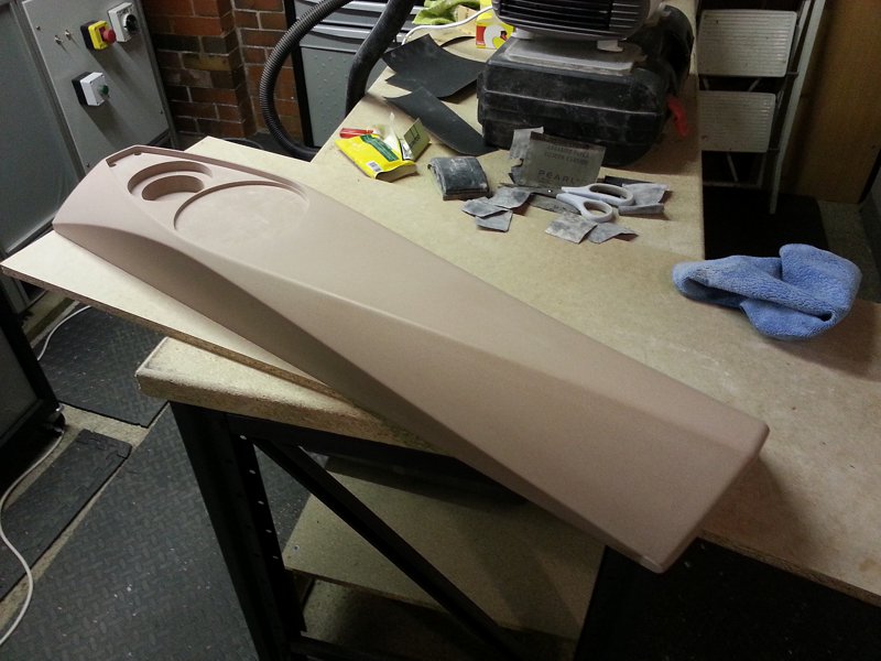
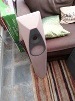
Quick post to show the waveguide insert. Not completely happy with it and needs tweaking.
This will be the last update on these for sometime as I'll be moving back over to the Apollo now that the lead has arrived.


This will be the last update on these for sometime as I'll be moving back over to the Apollo now that the lead has arrived.
Attachments


- Status
- This old topic is closed. If you want to reopen this topic, contact a moderator using the "Report Post" button.
- Home
- Loudspeakers
- Multi-Way
- Apollo Construction Diary