Cheap red LED for cathode bias, and a current source for the load. Make the current source adjustable with a pot, and you can tinker with distortion vs cathode to anode voltage.
My experience with the 6N1P-EV is that it produces the least distortion at about 105V anode to cathode. Since that is about the voltage you are shooting for at the grid of the second triode, direct connect them without a divider. Better frequency response.
Thanks for the feedback.
The 150 ohm on the EL84 seems OK, based on EL84 spec sheet the recommended value in UL mode is 130 ohm or 270 ohm per tube. The original value of 400 ohm in Tubecad was because the amp was PP triodes strapped.
- I have added the LED on the cathode of the first section of 6N1P.
If I add a CCS on the EL84 cathode I will only work as Class A, right ? Will I have less output power in Class A vs Class AB ? I'm aiming for 9-10W, not 5W since I already have a few SE amp with 5W output, I need something with more guts
")
For my original question regarding the bias current in the cathodyne, I'll build the amp and find out.
Thanks,
Eric
I am looking to make a small P-P amp and this little circuit seems to fit the bill nicely. This will also be my first P2P wiring attempt. I will however probably purchase Broskie's PS-4 psu board.
Info HERE
I'm building something very much like it right now. The design is not new. It has been well tested for more than a half century. The one I'm building is using a combination of eyelet boards and point to point wiring. I like to build the power supply by placing the diodes and snap-in and film caps on the eyelet board and the rest point to point. I tend to use a lot of coaxial wire too. But the circuit is very close to that.
I'm going for fixed bias rather than the cathode bias but that is just a small change. When I ran a Spice simulation of the amp I found that distortion is sensitive to the bias voltage. 0.2 volts can make a difference so I figured I would make it adjustable. You can make an adjustable cathode bias by replacing the fixed resistor with a suitable variable resistor. To avoid the need for a high wattage pot use a fixed resister in series to do most of the voltage drop, the pot only needs to control about a 2V range.
When you do build this spend the $$ to get some good transformers. That is what determines the sound quality.
If I add a CCS on the EL84 cathode I will only work as Class A, right ? Will I have less output power in Class A vs Class AB ? I'm aiming for 9-10W, not 5W since I already have a few SE amp with 5W output, I need something with more guts
To get 10 clean watts out of this you have to "push" it slightly. first you need the B+ as high as you are willing to go. Simulation shows I get lower distortion at high output power with a higher B+. I have verified this using a distortion meter and a variac controled bench power supply. I'd go right up to the data sheet limit for Va.
Along the same line you gain about 15 extra volts if you use a fixed bias rather than a cathode bias. If you are trying to get the maxium power out of a EL84 tube fixed bias, controlled by a 10 turn screwdriver adjustable pot is the way to go.
10W is a reasonable goal but don't expect that with a low b+ and cathode bias.
Real fixed bias with either a transformer or Dave Gillespie's EFB mod is better sonically according to Dave and many others that have tried it.
See this link @ diytube.com. His paper is linked to on the tronola.com site on the 5th post down.
diytube.com :: View topic - Improved SCA-35/ST-35 Performance
He basically says cathode bias works better with 10K or higher primary Output Transformers with EL84 PP and fixed is better with 8K or lower. Longer tube life too @ 25-27 mA too, even with the higher B+.
With the EFB mod or traditional fixed bias he's getting a clean full range bandwidth 17W/CH too.
Randy
Last edited:
Real fixed bias with either a transformer or Dave Gillespie's EFB mod is better sonically according to Dave and many others that have tried it. ...
He basically says cathode bias works better with 10K or higher primary Output Transformers with EL84 PP and fixed is better with 8K or lower. Longer tube life too @ 25-27 mA too, even with the higher B+....
That is correct but you don't have to do all of that or even get the best exact matching transformer. The first order effects of using fixed bias is very easy to understand: (1) You simply get 15 more volts to work with. It is the same as cranking up the B+ by 15V but without stressing the tube and (2) with cathode bias the voltage across the cathode resistor depends in the current through the tube. This is a kind of feedback and has the same pros and cons of any other feedback.
It is kind of like deciding if you are going to drive a car or ride a bike to work. That is the "first order" decision then which brand of car or bike matters but much less. Herethe bias method is the big decision then after that you have some details to work out but don't matter as much as people like to think.
Simulation is a great tool and the software is free.
I would recommend cathode bias (aka self bias) unless your goal is to extract the most performance from the amp. Many times you don't need that
I would recommend cathode bias (aka self bias) unless your goal is to extract the most performance from the amp. Many times you don't need that
I will use cathode bias, not fixed bias.
Not sure yet if I'll be using a resistor + cap or CCS on the EL84 cathode.
Last item before I go ahead ; Do you believe my 24k values for the cathodyne are OK ?
BR,
Eric
If we use the original design by Tubecad it's a typical PP Class AB output triode strapped EL84. Would it be very difficult to modify the amp to a Ultra Linear output and have lets say the first 3-4W in Class A and the remaining 4W-11W in Class AB.
Easy listening (low power) would be in Class A and when more power is required the amp would switch over to Class AB. This can easily be done with SS but what about while using tubes ?
6BQ5 spec sheet recommend 130 ohm for both tubes or 270 ohm on each EL84 while using a B+ of 300V, I believe changing the value for Rk on each EL84 for a specific value (which I ignore) will provide what I'm trying to achieve. Does anyone has any clue and how do I get there.
TIA,
Eric
Last edited:
Following the schematic you will have about 14V on the cathodes...independant resistors will just add more parts and complexity. Shared resistors allow you to at least easily deploy a balance pot.
I quickly switched mine over to fixed bias with a CCS...I have not taken measurements but am VERY happy with the results.
Oh..and I am running UL taps on the Edcor OPTs.
I quickly switched mine over to fixed bias with a CCS...I have not taken measurements but am VERY happy with the results.
Oh..and I am running UL taps on the Edcor OPTs.
the reason I'm asking is because I'm putting together an amp using a PC board I made. I have one 6BQ5PP with p2p, and now this one. i have the pc board made up so that I can use either a resistor/cap or CCS. I just want to get the best bang out of it.
Attachments
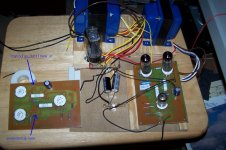
the reason I'm asking is because I'm putting together an amp using a PC board I made. I have one 6BQ5PP with p2p, and now this one. i have the pc board made up so that I can use either a resistor/cap or CCS. I just want to get the best bang out of it.
Nice work !
This is my first PP so please bear with me
Here is my beginner's questions ;
If you use the CCS for the EL84 shared cathodes, can you/should you bypass it with a cap ?
The available output power with a normal Class AB, UL mode, self bias is about 11W according to the EL84 spec sheet. Now, if I connect instead the CCS + cap. on the EL84 shared cathodes will the same output power be available or will I get less since it's Class A ?
I started drilling last night.
I have attached my schematics to visualize it better.
Thanks in advance,
Eric
Attachments
Nice work !
This is my first PP so please bear with me
Here is my beginner's questions ;
If you use the CCS for the EL84 shared cathodes, can you/should you bypass it with a cap ?
NO!
The available output power with a normal Class AB, UL mode, self bias is about 11W according to the EL84 spec sheet. Now, if I connect instead the CCS + cap. on the EL84 shared cathodes will the same output power be available or will I get less since it's Class A ?
I did not notice any percievable drop in power. I did not have the resistor bias for long. The CCS sounds much better. My speakers are not that efficient - 91db 2 ways and 4" CHR70's fullrange...the CHR70s are my favorite.
I started drilling last night.
I have attached my schematics to visualize it better.
Thanks in advance,
Eric
The key with the CCS is to make sure your PT allows for serious bias. I am at 81mA per channel ~ 40.5 per tube. I am using a balance pot to keep them idling the same.
Someday I will see how close I can get to 100mA per channel without redplating.
Also, beefy OPT's are key...the Edcors are great...Going off memory I think mine are the 25W 7.6K. Not sure I would go beyond 8K.
I have been running UL since the first time I fired it up. I have tried triode strapped and / or pentode mode on other amps and always come back to UL - personal preference.
The key with the CCS is to make sure your PT allows for serious bias. I am at 81mA per channel ~ 40.5 per tube. I am using a balance pot to keep them idling the same.
Someday I will see how close I can get to 100mA per channel without redplating.
Also, beefy OPT's are key...the Edcors are great...Going off memory I think mine are the 25W 7.6K. Not sure I would go beyond 8K.
I have been running UL since the first time I fired it up. I have tried triode strapped and / or pentode mode on other amps and always come back to UL - personal preference.
Thanks a lot for the help !!
I also have a pair of OPT like yours but I'm keeping them for a Dynaco ST-35 clone later on. Can't you tell I really like EL84. I also favor UL connection.
This amp will be driving a pair of enabled CSS EL70 by Planet10
I have chosen the slanted floor stander.Rgds,
Eric
nice I have the EL70's in the fonken floor standers for my front channel speakers in my TV room...both were DIY enabl'd but one met its demise with a Wii remote...the other one is in but I have not gotten around to enabl-ing it yet...
GREAT little drivers...
The CHR70's are quite solid too...
GREAT little drivers...
The CHR70's are quite solid too...
Hi,
I just finish building the amp and its sound really good. I tried both Class A with the CCS and Class AB with a resistor + cap (cathode bias) and I prefer Class A.
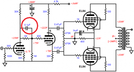
Could someone tell me the role of the circled cap on the attached dwg. Should this be a good quality cap like a PIO or an ordinary non polarized will do ?
Does the signal goes through it or is this just an AC bypass ??
BTW, I used a LED on the driver's cathode and a CCS (80 mA with LM317) on the EL84 cathodes (without bypass cap). I'm using UL connection, not triode.
Output power (before clipping) with B+ of 300V on anodes of EL84 is
6W rms (Class A) and if I use a 135ohm, 5W resistor (Class AB) instead of the CCS I get 10.5W rms.
Thanks,
Eric
I just finish building the amp and its sound really good. I tried both Class A with the CCS and Class AB with a resistor + cap (cathode bias) and I prefer Class A.
Could someone tell me the role of the circled cap on the attached dwg. Should this be a good quality cap like a PIO or an ordinary non polarized will do ?
Does the signal goes through it or is this just an AC bypass ??
BTW, I used a LED on the driver's cathode and a CCS (80 mA with LM317) on the EL84 cathodes (without bypass cap). I'm using UL connection, not triode.
Output power (before clipping) with B+ of 300V on anodes of EL84 is
6W rms (Class A) and if I use a 135ohm, 5W resistor (Class AB) instead of the CCS I get 10.5W rms.
Thanks,
Eric
Attachments
Last edited:
See this thread, starting with post #2. A good metallized polypropylene would be fine used here.
http://www.diyaudio.com/forums/tubes-valves/121693-direct-coupling-question.html
http://www.diyaudio.com/forums/tubes-valves/121693-direct-coupling-question.html
Hi,
I just finish building the amp and its sound really good. I tried both Class A with the CCS and Class AB with a resistor + cap (cathode bias) and I prefer Class A.
Could someone tell me the role of the circled cap on the attached dwg. Should this be a good quality cap like a PIO or an ordinary non polarized will do ?
Does the signal goes through it or is this just an AC bypass ??
BTW, I used a LED on the driver's cathode and a CCS (80 mA with LM317) on the EL84 cathodes (without bypass cap). I'm using UL connection, not triode.
Output power (before clipping) with B+ of 300V on anodes of EL84 is
6W rms (Class A) and if I use a 135ohm, 5W resistor (Class AB) instead of the CCS I get 10.5W rms.
Thanks,
Eric
Last edited:
Thanks for the answer, I will put a quality cap.
One more question ; I have now hooked up the amp to a CD player and the gain is way too much so I was thinking about adding some 4-5 db of global NFB to bring down the overall gain a bit. The gain starts strong even at 11 o'clock on the volume dial and then not much increase in power up to 3 o'clock...
My schematic is like the one in post no.73. I want to keep the LED by itself on the driver's cathode and I do NOT want to add a series resistor with the LED. Is there a way to add global feedback in these condition ?
Any suggestion from the tube wiz of this forum.
TIA,
Eric
- Home
- Amplifiers
- Tubes / Valves
- Anyone ever made the EL84 P-P circuit referenced on the Tubecad Journal site?