Blumlein’s Garter Circuit Revisited
Blumlien Garters balance the idle current through the two halves of the P-P OPT primary.
I have done this to several amps. Even the one I listen to...
Well worth a look and listen.
Matching the lower sense resistors assures better balance, forever... well, longer than fixed bias.
Happy Ears!
Al Marcy
PS The balanced current even improves old transformers that were kinked by the inglorious balanced bias voltage of a shared cathode resistor. It just keeps getting better.
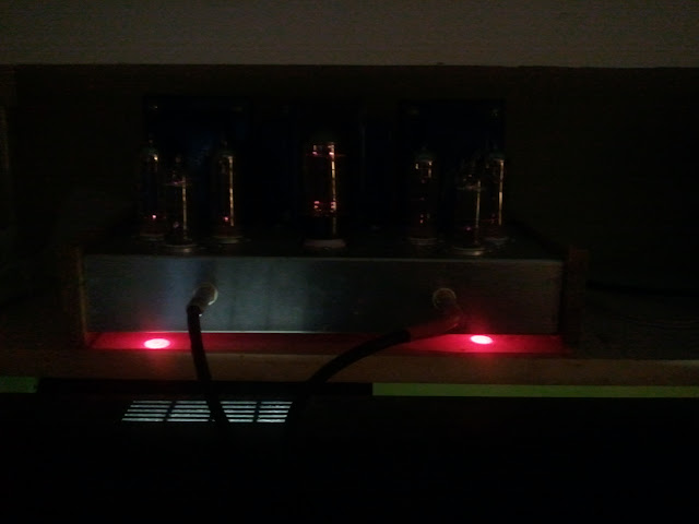
You know, I'm looking at the pic above.....
The way I did mine, I used 1 x 6N1P as the driver for both channels, and then a second one for the splitter. The way you have yours laid out, you must have used 1 6N1P as driver and splitter for each channel.
Is there any difference which way you do it?
Fran
The way I did mine, I used 1 x 6N1P as the driver for both channels, and then a second one for the splitter. The way you have yours laid out, you must have used 1 6N1P as driver and splitter for each channel.
Is there any difference which way you do it?
Fran
They way I wired mine, one tube is dedicated per channel. One half is the gain, the other half is the splitter.
I suppose there are advantages to either approach - I, for example, would always have to use the same input tube pair, and you could roll different input tubes since each tubes half is dedicated to the same "job". You would need to make sure that each tube's sections were pretty closely matched. I'm sure there are others...
I suppose there are advantages to either approach - I, for example, would always have to use the same input tube pair, and you could roll different input tubes since each tubes half is dedicated to the same "job". You would need to make sure that each tube's sections were pretty closely matched. I'm sure there are others...
Just thought I'd do an update.
I worked through the various mods suggested here, added in the LED and did the CCS with a LM317 on the output, set to 40mA per valve. Anyway, I kinda thought I lost some of the initial magic. Also the power transformer was getting uncomforatbly hot.
So I decided to throttle back a little and cut the CCS back to ~30mA per valve. Now I got a fair bit of the magic back. Better resolution and space and soundstage. The PT runs a little cooler too. Now the question is.... was the pressure on the Pt causing the loss in SQ, or was it the current through each valve?
So maybe broskie wasn;t too far out when he specified that 400R on the EL84 cathodes.
Fran
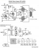
XPWR007 120V 60Hz to 550 volt (275-0-275) @ 200mA,
6.3 volt @ 6A, 5.0 volt @ 3A
Power Transformer
RoHS Compliant
Thats the PT I am using...at 100mA total draw it gets pretty warm but not "hot"...
What B+ are you running at the inputs and el84's? I am running within a couple volts on the original tubecad schematic ~340V B+
6.3 volt @ 6A, 5.0 volt @ 3A
Power Transformer
RoHS Compliant
Thats the PT I am using...at 100mA total draw it gets pretty warm but not "hot"...
What B+ are you running at the inputs and el84's? I am running within a couple volts on the original tubecad schematic ~340V B+
Played it with some 6DJ8's today...sounded lovely...
You are using led bias + the lm317 ccs right?
Concertina...please help.
Hi,
Sorry to open an old thread but from the comments this sounds like a great simple amp to build. I have built many SE and SET but this will be my first PP.
I had a question regarding the bias current for the concertina...
For the first stage using the 6N1P-EV, I really enjoy the sound (from a SE amp) when the cathode bias is set to 9mA (Vplate of 200V, Vk of 1.8V using Rk of 200 ohm) how about the concertina Ra and Rk values..., do the concertina has to be bias at a certain value in order to optimise it ? My biggest concern is : will the overall sound be different if I choose 4-5mA vs 9mA in the concertina section ?
Please verify my proposed value. Feel free to comments of the overall schematics before I start punching holes..
TIA,
Eric
Attachments
Last edited:
Looks OK, I went with the 30K plate load for both sections and Rk and it works good for other tubes like 6cg7 and 6dj8, although 6n1p is my favorite.
150ohm on the EL84 cathodes seems a little "hot"
I would also suggest a couple mods
1. Balance pot on the EL84's (10-25 ohm depends how well matched your tubes are)
2. CCS on the EL84 cathodes
3. Red LED on the front section of the input tube.
150ohm on the EL84 cathodes seems a little "hot"
I would also suggest a couple mods
1. Balance pot on the EL84's (10-25 ohm depends how well matched your tubes are)
2. CCS on the EL84 cathodes
3. Red LED on the front section of the input tube.
Last edited:
Cheap red LED for cathode bias, and a current source for the load. Make the current source adjustable with a pot, and you can tinker with distortion vs cathode to anode voltage.
My experience with the 6N1P-EV is that it produces the least distortion at about 105V anode to cathode. Since that is about the voltage you are shooting for at the grid of the second triode, direct connect them without a divider. Better frequency response.
My experience with the 6N1P-EV is that it produces the least distortion at about 105V anode to cathode. Since that is about the voltage you are shooting for at the grid of the second triode, direct connect them without a divider. Better frequency response.
- Home
- Amplifiers
- Tubes / Valves
- Anyone ever made the EL84 P-P circuit referenced on the Tubecad Journal site?