Hi All,
I encourage anybody who builds a minimal reactance psu (or any other CCS - shunt reg - CCS psu for that matter) to try a shunt where the AC duties are carried out by the tube element (the AC output is fed back to the tube grid via a capacitor). See http://www.tubecad.com/july99/page13.html for details.
I found this to be a rather large improvement on the topology with the TL431 carrying out AC duties, which sounded somewhat congested and overly 'tight' rather like a high nfb amp.
Use a really good cap for the AC feedback (say Auricap or better) and cathode bypass (Black gate was best by a mile here I'm sorry to say), and you may get quite a surprise.
CCS - shunt - CCS has been around for a while, being championed recently by Gary Pimm in his designs. The only new concept in the minimal reactance topology is taking psu capacitor size to the smallest practical value.
Banned from the DIY/Tube section for telling the world that MQ-Mike had his head up his backside when it came to understanding how the transformers work( remember the PP, class A loading discussion? )
Hi Douglas,
Did you know that I am a MQ distributor for Europe? I followed the whole discussion on AA. The thing is people get too serious and personal. When they do get too serious and personal..... I just back off. Don't know enough to argue anyway...and when I don't agree I just pull out of the discussion and do my own thing anyway in my amps. I have to admit I think you went too far when saying MQ's work was a ripp- off and I'm not saying that because I'm a MQ distributor. That was before I became one. Transformers remain a lot of handwork. Can't blame a man for asking an honest wage. But let's not get into a discussion. It is only my point of view.
Regards,
Bas
all tube ccs/shunt regulator
I was thinkulating about the subject of combining ccs/shunt regulators, and wondered why it couldn't be done with all tubes. There's plenty of unwanted miniature triode-pentodes that might work fine for this application when combined with a voltage reference tube, as shown in the conceptual schematic I attached. The OA2 or OB2 and 1M safety resistors minimize and equalize the filament/cathode potentials to allow regulated voltages of up to over 300V safely. Some standard measures may be helpful to reduce any noise from voltage reference elements.
I was thinkulating about the subject of combining ccs/shunt regulators, and wondered why it couldn't be done with all tubes. There's plenty of unwanted miniature triode-pentodes that might work fine for this application when combined with a voltage reference tube, as shown in the conceptual schematic I attached. The OA2 or OB2 and 1M safety resistors minimize and equalize the filament/cathode potentials to allow regulated voltages of up to over 300V safely. Some standard measures may be helpful to reduce any noise from voltage reference elements.
Attachments
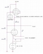
Btw, that grid #2 bias sort of hurts the CCS regulation, but there's compactrons out there that have a second triode which can be used as a follower or used inverting tapped off the existing triode grid divider, possibly ditching the neon bulb in the process, in a scheme to separately sink that current path") The latter scheme may even allow a trim adjustment to maximize the CCS impedance; just thoughtubrating here.
The latter scheme may even allow a trim adjustment to maximize the CCS impedance; just thoughtubrating here.
Btw, it's surprising what can be accomplished with a couple of trim circuits. I have designed a more conventional series pass tube regulator using a single miniature dual element triode and 0A2 that, with fixed resistive compensation & a simple potentiometer trim circuit to optimize input noise rejection, has over 60db of AC input noise rejection and about a 10 ohm output impedance.
The latter scheme may even allow a trim adjustment to maximize the CCS impedance; just thoughtubrating here.Btw, it's surprising what can be accomplished with a couple of trim circuits. I have designed a more conventional series pass tube regulator using a single miniature dual element triode and 0A2 that, with fixed resistive compensation & a simple potentiometer trim circuit to optimize input noise rejection, has over 60db of AC input noise rejection and about a 10 ohm output impedance.
Care to share a schematic?thoriated said:I have designed a more conventional series pass tube regulator using a single miniature dual element triode and 0A2 that, with fixed resistive compensation & a simple potentiometer trim circuit to optimize input noise rejection, has over 60db of AC input noise rejection and about a 10 ohm output impedance.
Well Bas...
I don't remember saying Mike's work was a rip-off. I have said I refuse to pay for it, but this matches a concurrent refusal on his part to sell it to me.
The PPS autoformer phase splitter design, or at least the originals I tested for him came about after a few hour long telephone brainstorming design session. We argued about how best to interleave the bobbin, and over how to interpret the measurements I would take. When I posted the prelim measurements in the tube DIY forum, I clearly stated it was 'we' thing.
Mike did indeed take full credit for that design later, and on top of that explicitly denied that I had anything to do with it. He firther lied by saying it was out of the goodness of his heart that he shared the design with me and that I had agreed to keep it confidential.
It just did not happen that way, and when he called me on the 'phone Labor Day 2004 to argue with me in person over the workings of a CT choke, the relationship came apart when I refused to admit that he was right, and he hung up on me.
I don't expect that this post will remain, considering your moderator status. I don't recall saying that Mike's work was a rip-off. My complaint is that Mike claimed to have acted alone when no such thing happened. Jean-francois Lessard had complained at about the same time about the inadequacy of the 173 for autoformer PS duty. His numbers on the MQ product were worse than what I got from an item with 5x the inductance. The improved design was not his alone, and the facts do not require your belief in them to be true.
None of this has anything to do with the work involved with actually building a TX. It does not make any claim about the skill with which Mike creates the MQ TX's.
It is all about the way Mike sees fit to conduct business. Like claiming ownership and control rights over a never-patented 1948 output TX design I have modified for E-Linear use. I have no issue with the MQ products, only with the less-than-honourable way he conducts himself in public.
Things like publishing private edited and misrepresented email correspondence w/o permission on his company website all point the same way. I am sorry to see you mixed up with such a businessman. Please be careful.
cheers,
Douglas
Re: Well Bas...

Bandersnatch, please be aware that such a comment impugns the integrity of all moderators. If you will look in the Forum rules, you will discover that we are all 7' 6", super fit, and carry a brace of Colt 45s. Please take care...
Bandersnatch said:I don't expect that this post will remain, considering your moderator status.
Bandersnatch, please be aware that such a comment impugns the integrity of all moderators. If you will look in the Forum rules, you will discover that we are all 7' 6", super fit, and carry a brace of Colt 45s. Please take care...
all tube ccs/shunt tube regulator
Hi Thoriated,
I can vouch that your conceptual circuit will work quite well, because with the exception of a very large zener instead of the gas tube and some other trivial differences I used just about this topology in one of my early pre-amplifier designs. (About 1990)
Unlike many here I am not convinced that it is inherently superior to any other well executed and designed topologies, however I do prefer all tube implementations for a variety of reasons including robustness in the face of line transients, tube failures, and the like. (Sound quality as well.)
I will note that my target was not really minimal reactance at all, but for some reason at the time I thought a supply with reasonable source/sink capabilities might just sound better. It worked well with very small amounts of capacitance, but I was in a phase where I liked and used lots of capacitance, that it didn't make any difference to the performance of the powered circuit as long as good small film cap remained on the output was an indication of its good performance.
Note that I never adequately proved my conjecture that this topology was any better than a really good tube based series pass regulator in class a applications.
Kevin
- Status
- This old topic is closed. If you want to reopen this topic, contact a moderator using the "Report Post" button.
- Home
- Amplifiers
- Tubes / Valves
- Anyone build a Minimal Reactance PSU?