I forgot to add the idle power...if 50mA bias then that's about 5W. So now it's 26W and pretty close to what you have measured.Aha, Thank you for working / (Explaining) that out. As I mentioned, a formula I can stare at for ages, and it makes no sense, But give the formula with an example, then I can start to make sense of them.
So looks like we're good")
The formula for FET power is tricky because you have to integrate the Vds x Is over a quarter cycle and divide by two. It isn't as easy as the Vrms x Irms formula for the load.
Edit: Using a spreadsheet gives 21.2W. Still not far off your bench measurements and the thermal resistance is a guess. This is the price for having high power rails - poor efficiency at low power outputs.
That would explain why when I first ran them up on 15v rails, at just below clipping, they ran very cool or at least just warm.
Maybe I should put that power supply in, I don't really need 80 or even 50 watts these days
My Valve Quads, only rated at about 15w, are plenty loud enough for normal listening, and still have plenty in reserve.
For most modern speakers the power into 4 Ohms is far more important.
An amplifier that can do 50W@8 and doubles to 100W@4 is plenty for a normal room size
That require 28V peak, which allowing for Vgs and the LTP drops, is why my tweak uses 40V rails. That should still give around 70W@8 as Vgs will be lower.
The difference in volume between 70W and 100W is very small
For most modern speakers the power into 4 Ohms is far more important.
An amplifier that can do 50W@8 and doubles to 100W@4 is plenty for a normal room size
That require 28V peak, which allowing for Vgs and the LTP drops, is why my tweak uses 40V rails. That should still give around 70W@8 as Vgs will be lower.
The difference in volume between 70W and 100W is very small
Yes, I agree, But.... at the moment I can't really justify the expense of buying a new Toroid.
This is a basic modification with modern bjts, for single die 8A outputs
40V rails keep peak power down for realistic speaker loads and a current source on the input LTP makes the bias independent of supply.
Looking at the schematic in post 116
What is the advantage of using the 47uf capacitor across the bias setting potentiometer?
At high frequencies, when the VAS second LTP and current mirror is swinging positive or negative current in RV1 will tend to vary from the dc value, causing the crossover quiescent to varyWhat is the advantage of using the 47uf capacitor across the bias setting potentiometer?
What’s R12 do?
It also gets pretty Hot, I noticed in the later versions they had upped the wattage from .5 watt to 1 watt, I have ceramic bead standoffs on the legs of mine.
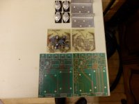
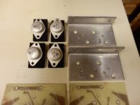
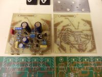
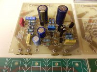
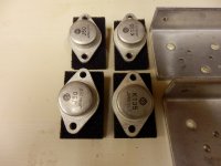
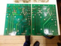
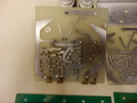
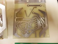
some pictures of my construction
Attachments
It also gets pretty Hot, I noticed in the later versions they had upped the wattage from .5 watt to 1 watt, I have ceramic bead standoffs on the legs of mine.
Ah - that explains it then. It looks like it's to dissipate power that otherwise would have to be dissipated by the little TO-92 driver, allowing more current in that stage.
Which R12 are you talking about? On my schematic it's a 47 ohm. With Vout=0V there will typically be about 5mA flowing through it and 250mV across it. Not much impact on TR5 which will have the same current but nearer 50V across it.
If this is the same R12 then I am confused if it needs to be 1W and have thermal spacers put on it.
If this is the same R12 then I am confused if it needs to be 1W and have thermal spacers put on it.
- Status
- This old topic is closed. If you want to reopen this topic, contact a moderator using the "Report Post" button.
- Home
- Amplifiers
- Solid State
- Any Maplin MosFet Amp Guru's on here?