.
Personally I think to much time has been spent on the subject for hobbiest application as it pertains to the original topic. A dac hobbiest knows how to safely ground his creation, those that don't can find many resources on the web with good explaination.
I keep coming back to this thread, the latest post on the esdesigns thread where emi isn't considered due to "health" reasons just left me shaking my head. Mentions possibilities of using a computer to controll the scandisk, doesn't even come close to bringing that juke box(transport+dac+amp+speakers all dependeant on one another) into a modern age.
More common sense here than in years of posts on the other thread, would be good to keep it that way.
Hi,
They may very well be different speed in reality. JUst get the fastest on the list in each case.
Ciao T
Popping 74HC175 into digikey and selecting "in stock" and "through hole" I get two options
...
Popping 74HC4040 into digikey and selecting "in stock" and "through hole" I get three options
...
Are this chips really different speeds or is it just an artifact of coming from different companies?
They may very well be different speed in reality. JUst get the fastest on the list in each case.
Ciao T
Joshua_G, it's too bad you didn't ask this question a few months earlier:
Raindrop was selling a WM8805 to NOS TDA1541 with no I/V. Although a train-wreck like T says, there's less to go off the track and for $90 it will be a fun thing for me to play with. I emailed him/her and they aren't offered anymore.
…
Hi Jeff,
Thank you, however I have no interest in train-wrecks. I'm looking for something affordable to me which will be better than Thorsten's AMR CD-777 which I own.
When the PCB design is less than perfect, better results are attainable on Vero-board.
As for Thorsten's Vero-board version suggested here, it looks like a very good start, however it isn't a complete solution and I believe Thorsten has something better being cooked.
I keep coming back to this thread, the latest post on the esdesigns thread where emi isn't considered due to "health" reasons just left me shaking my head.
Just for clarity, I mentioned two things:
1) Wireless communication causes unwanted EMI (Electro magnetic Interference).
2) Official studies show that wireless communications cause health risks.
Mobile phone safety. The real truth about the hazards explained for the layman.
Then I hope you live in a cave, surrounded by a Farayay cage, because EMI is all over you. Radio, TV, satellites, radars, computer/TV power supplies, the belowed fluorescent eco-lamps...
Even the power wires in the walls generate EMI.
But nothing compare with the Sun that generates tons of EMI, enough to heat up the Earth.
Even the power wires in the walls generate EMI.
But nothing compare with the Sun that generates tons of EMI, enough to heat up the Earth.
Then I hope you live in a cave, surrounded by a Farayay cage, because EMI is all over you. Radio, TV, satellites, radars, computer/TV power supplies, the belowed fluorescent eco-lamps...
Even the power wires in the walls generate EMI.
But nothing compare with the Sun that generates tons of EMI, enough to heat up the Earth.
Easy, i am sure he did a google on EMI as well...🙂
i think there is nothing wrong with someone considering every possible negative effect the design might have, even if not everyone agrees.
google will get results with oppinions that are true and results that are false.
Even some "government" funded studies will be biased, because of political interests behind those money.
That's why we are on a forum, to discuss and weed out the legends and stories from reality. Reality is that EMI do not pose a health risc. Otherwise life on Earth would be long gone due to solar EMI (infrared and light are Electro-Magnetic too).
Only when you go in higher energy photons (higher frequency EM - like UV) there can be some effects.
Saying that a lower than 1GHz EM field would have significant effects (besides heating) compared to the IR or light (over 300THz) or UV (3PHz) is nonsense.
Last edited:
Guys if you want to discuss the possible health effects of EMI, please start a new thread. I'm sure you'll get a lot of input.
I'd like to get this thread back on track--TDA1541 kits and how to make them better.
Cheers,
Jeff
I'd like to get this thread back on track--TDA1541 kits and how to make them better.
Cheers,
Jeff
Sorry I brough up the EMI, was just pointing out that this is a good thread. To me if a DAC doesn't work with foobar or hell even itunes forget about it.
To get back to reality. Any comments on this output stage by one of the most talented digital guys out there so this is his analog work but I thought it somewhat interesting, I think I am afraid it must have a very high input impedance, not sure how it would be calculated though:
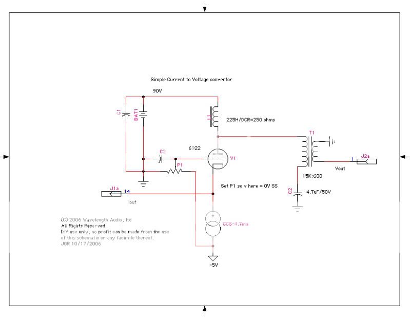
Edit: My guess is the input impedance is basically the grid to cathode impedance in parallel with the top of the CCS which would be high enough as to be inconsequntial?
To get back to reality. Any comments on this output stage by one of the most talented digital guys out there so this is his analog work but I thought it somewhat interesting, I think I am afraid it must have a very high input impedance, not sure how it would be calculated though:
Edit: My guess is the input impedance is basically the grid to cathode impedance in parallel with the top of the CCS which would be high enough as to be inconsequntial?
Last edited:
The impedance as seen looking into "iout" is 1/gm which for a 6922 is something like 10mS so thus about 100ohm or so.
But since Vout is determined by what you load the transformer with I would make sure its always well defined (Ie put a resistor across the transformer secondary)
Also since tubes start cold you need something to protect the TDA (Back to back diodes)
But since Vout is determined by what you load the transformer with I would make sure its always well defined (Ie put a resistor across the transformer secondary)
Also since tubes start cold you need something to protect the TDA (Back to back diodes)
The impedance as seen looking into "iout" is 1/gm which for a 6922 is something like 10mS so thus about 100ohm or so.
But since Vout is determined by what you load the transformer with I would make sure its always well defined (Ie put a resistor across the transformer secondary)
Also since tubes start cold you need something to protect the TDA (Back to back diodes)
Interesting, so a a 6c45p or other what I call space age tube with gm of 50 would give a respectable 20 ohms input impedance. With a EC8020 we get 15 ohms input impedance.
The OPT 15k:600 is commonly used in tube preamps so I 'm not too concerned, the reflected load on the tube will be very high which is good for linearity.
With the tda1541 I think it has a high tolerance to output dc levels, need to look into where I saw that. The right CCs and tube rectification may make the protection diodes unnecessary.
Best thing i like is no need to add a jfet ccs to kill the -2ma offset as you do with passive I/V (per Ove's experiements, I know Thoresten doesn't agree).
Certainly slooks like a promising dac tube stage then.
Lets bring the discussion back to implementing the 1541.
I doub't there can be anything much to be gained by reclocking the WCLK and the DATA input on the dac. Since the dac does not do anything but sample the values on WCLK and DATA at positive edges of BCLK. (The bclk edge is paramount tough) When they change state should not be of much importance this is not the whole truth tough.
We know the TDA inputs looks like two diodes (referenced to dgnd) and a parallell capacitance of 10pf or so (referenced to -15V this would be the IC substrate). Limiting the currents injected into the substrate is the whole reason for applying slewrate limits on the input. (since the amount of current injected is directly related to the slewrate and the size of the capacitance)
Since current can only be injected into a capacitance when there is voltage change across and if the internal diodes will clamp the positive going voltage it really should be enough by just applying a suitably large resistor + a capacitor to limit the slewrate (in practice there is a finite time a diode needs to turn on but we should be comfortably below that limit here and dc current flowing through the diodes into dgnd also should not be important) and bandwidth limit the resistor noise so we dont increase the phase noise unnecesarily from adding a resistor.
Now looking at a sample per sample average basis there will always be the same amount of bclk and wclk transitions (well depending on 32 or 64fs frames but thats not important here) any deviation in time on theese with regard to current injected in the substrate should be completely evened on a sample per sample basis. Especially if a suitably low I/V impedance is used so that a comparatively large decoupling capacitance (to gnd) can be added to the TDA current outputs to filter any noise voltages apearing. (if the I/V impedance is really low a larger capacitance can be used, all else being equal)
That leaves the data input. Since we are using PCM the input words are realted to the output current value. Thus there is a data related factor to the currents injected on the data input, maybe not all that bad since the amount of noise should be proportional to the number of bit transitions in the data and this is not directly related to the output value.
But these variations should completely swamp any minute difference from timing variations from when the transitions occur.
It would however be very interesting to test this in practice, what would be a good way to inject a controlled amount of phase noise to a data line?
Two unbuffered inverters in series, with a noise modulated supply voltage?
Last edited:
Back to the digital side. I agree with your thinking and found an analogous situation when working wtih the PMD100 (except there you don't want to reclock the bitclock), but similiar concept, reclock the line that matters.
But I still think we are puting the cart before the horse. The bigger issue is how we will put the master clock with the DAC to do this "paramont" bclk reclocking, how do we isolate the clock and feed it back to the usb chip or soundcard without introducing the computers ground or an extremely noisy component on the dac board? I think an adum chip on the DAC board is a "bit" crazy. Is a GMR as much of an issue, with introducing a lot of noise on both ends?. I recently saw a recomendation to use a certain high bandwidth transformer which should have minimal phase shift to obtain a lock but it hasn't been tested at the 22.579 mhz and would certainly require some buffering scheme.
Now if the "ultimate fifo" project on this forum gets into production then we have something to talk about, otherwise I think the best bet for the hobbiest is going to be a wm8804 spdif input sans reclocking and leave room on the veroboard to insert the fifo if it orks out. Thats my plan and hence the shift toward looking for a good analog stage for the tda1541. Right now unless you have come up with something proven short of the classic vxco pll we are looking at a disc player and not a DAC if we want to reclock?
Hi,
While this correct to a point, there are many reasons why we may wish to reclock all inputs as there is a propagation delay through any reclocker...
No WE don't and it does not really look like that either. It's not even a very good first order approximation.
The slew rate limiter is indeed to reduce current into the substrate, but that is not the sole or even main reason for jiggery pokery on the TDA1541 Inputs.
Your analysis is way off.
You are forgetting the data....
I agree, the leakage in the substrate is modest, especially if and when the voltage swing is minimised.
But as said, minimising the noise injection into the substrate is not the main issue.
Ciao T
I doub't there can be anything much to be gained by reclocking the WCLK and the DATA input on the dac. Since the dac does not do anything but sample the values on WCLK and DATA at positive edges of BCLK. (The bclk edge is paramount tough) When they change state should not be of much importance this is not the whole truth tough.
While this correct to a point, there are many reasons why we may wish to reclock all inputs as there is a propagation delay through any reclocker...
We know the TDA inputs looks like two diodes (referenced to dgnd) and a parallell capacitance of 10pf or so (referenced to -15V this would be the IC substrate).
No WE don't and it does not really look like that either. It's not even a very good first order approximation.
Limiting the currents injected into the substrate is the whole reason for applying slewrate limits on the input. (since the amount of current injected is directly related to the slewrate and the size of the capacitance)
The slew rate limiter is indeed to reduce current into the substrate, but that is not the sole or even main reason for jiggery pokery on the TDA1541 Inputs.
Since current can only be injected into a capacitance when there is voltage change across and if the internal diodes will clamp the positive going voltage it really should be enough by just applying a suitably large resistor + a capacitor to limit the slewrate (in practice there is a finite time a diode needs to turn on but we should be comfortably below that limit here and dc current flowing through the diodes into dgnd also should not be important) and bandwidth limit the resistor noise so we dont increase the phase noise unnecesarily from adding a resistor.
Your analysis is way off.
Now looking at a sample per sample average basis there will always be the same amount of bclk and wclk transitions (well depending on 32 or 64fs frames but thats not important here) any deviation in time on theese with regard to current injected in the substrate should be completely evened on a sample per sample basis.
You are forgetting the data....
That leaves the data input. Since we are using PCM the input words are realted to the output current value. Thus there is a data related factor to the currents injected on the data input, maybe not all that bad since the amount of noise should be proportional to the number of bit transitions in the data and this is not directly related to the output value.
I agree, the leakage in the substrate is modest, especially if and when the voltage swing is minimised.
But as said, minimising the noise injection into the substrate is not the main issue.
Ciao T
If you have more information on how the inputs actually do look like, I would be most interested to share that information.
If it does not look like two diodes in series with a cap to the substrate then things are different, so please do elaborate.
If it does not look like two diodes in series with a cap to the substrate then things are different, so please do elaborate.
Back to the digital side. I agree with your thinking and found an analogous situation when working wtih the PMD100 (except there you don't want to reclock the bitclock), but similiar concept, reclock the line that matters.
But I still think we are puting the cart before the horse. The bigger issue is how we will put the master clock with the DAC to do this "paramont" bclk reclocking, how do we isolate the clock and feed it back to the usb chip or soundcard without introducing the computers ground or an extremely noisy component on the dac board? I think an adum chip on the DAC board is a "bit" crazy. Is a GMR as much of an issue, with introducing a lot of noise on both ends?. I recently saw a recomendation to use a certain high bandwidth transformer which should have minimal phase shift to obtain a lock but it hasn't been tested at the 22.579 mhz and would certainly require some buffering scheme.
Now if the "ultimate fifo" project on this forum gets into production then we have something to talk about, otherwise I think the best bet for the hobbiest is going to be a wm8804 spdif input sans reclocking and leave room on the veroboard to insert the fifo if it orks out. Thats my plan and hence the shift toward looking for a good analog stage for the tda1541. Right now unless you have come up with something proven short of the classic vxco pll we are looking at a disc player and not a DAC if we want to reclock?
I'm going to try an analog PLL soon similar in design to that in the old pacific microsonics appnote's but with much much improved parts. I've also made provisions to try the WCLK slaving of the signal source. See how it turns out.
Hi,
The input is a long tailed pair biased by two diodes.
Ciao T
If you have more information on how the inputs actually do look like, I would be most interested to share that information.
The input is a long tailed pair biased by two diodes.
Ciao T
Hi,
The input is a long tailed pair biased by two diodes.
Ciao T
By bias you mean the diodes form the reference to which the inputs are compared?
It does sound nasty to overdrive a bjt diffstage especially considering the base emitter diode.
The tail of the LTP is that a current source? going to?
Last edited:
Feeding back the bitclock/masterclock/other sync signal to the soundcard is easy, as long as your soundcard supports it.
There are really cheap Envy24-based cards, with Tremor chipset - they go for 5-10$ a card, have tappable i2s lines, and onboard xtals for 44100 and 48000 sampling rates.
You can take the 44100 xtal from the board, throw it on the dac board + reclock the i2s lines with it. Then you feed the Tremor with that clock directly.
Easy, cheap, and you can withdraw all the SPDIF conversions all together, by throwing-in RS485 transceivers on both ends of transmission line.
You get slight ground break, DAC-sourced clock, and no SPDIF.
In the other hand, you get PC-only DAC. High quality soundcard, that's it.
You can use any soundcard, which have SPDIF input, and which is able to lock on external SPDIF, and sync-up with it.
Then you use reclocker/clock distributor on DAC side, and feed the soundcard back with a sync signal in the SPDIF envelope.
SPDIF has simple square wave signal for digital "0", with 64fs rate. You can form it by passig the MCLK thru 1/4 divider + transformer.
Third, but not last solution - is to use Infrasonic Quartet soundcard, which can thake 128fs/256fs sync signal directly, bypassing the spdif thing. It has BNC connectors for masterclock in/out.
All you need to do to eliminate the jitter, is to clock the DAC with local fixed clock (no VCOs), and control the incoming data flow by feeding back the clock to digital source.
You need, as stated several times above, to badwidth-limit the data lines going to the TDA. Attenuation would be nice too.
You'll need to do this on the I2S source end, so the HF signal edges would be passed by BW-limiting capacitors back to the I2S source ground, not the DAC's ground.
Last edited:
Hi,
Yup.
+5V.
Ciao T
By bias you mean the diodes form the reference to which the inputs are compared?
Yup.
The tail of the LTP is that a current source? going to?
+5V.
Ciao T
- Status
- Not open for further replies.
- Home
- Source & Line
- Digital Line Level
- Any good TDA1541A DAC kit?