Did you have to stick a transformer on it?.............
there is a better way than ask him this question: tell him in at least 28 postings how many clamping diodes he has to build into that circuit.
johnferrier said:But, kind of in the spirit of simplify, I dropped down to a single stage--the output. Obviously, it will have no gain. I'm not interested in loud listening levels.
This works great. We've built headphone "amps" like this before, and they sound wonderful.
Attachments
![headphone[1].gif](/community/data/attachments/19/19294-f0c6fd92a6dac2b9d171b8b3a9a0ddc2.jpg)
Transformers and JFETs...
...are "old school" so to speak.
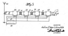
From the original 1930 JFET patent. The boxes represent JFETs. Looks like ZFB to me.
Also, for those that think that today's patent process is slow, it was filed in Oct. 1926 and granted in Jan. 1930. That is about the duration these days.
...are "old school" so to speak.
From the original 1930 JFET patent. The boxes represent JFETs. Looks like ZFB to me.
Also, for those that think that today's patent process is slow, it was filed in Oct. 1926 and granted in Jan. 1930. That is about the duration these days.
Attachments
Charles,
regarding to your headamp schematic with 2SK170 & 2SJ74, did you chose the Rg regarding to the Nf for respective FET?
The sad thing is that the P-ch have about 3-4 times higher C...
You talked a bit about cascodes, just wanted to ask your opinion wether you think an input FET transistor should be cascoded with same type of transistor or a BJT instead, pros and cons?
Ultima Thule said:just wanted to ask your opinion wether you think an input FET transistor should be cascoded with same type of transistor or a BJT instead, pros and cons?
It depends on what you are trying to do. A cascode will offer two benefits:
- Elimination of Miller capacitance on the input device. (standard or folded cascode)
- Ability to use a low-voltage input device in a high voltage circuit. (standard cascode only)
Unless I really needed one or both of these advantages, I would keep the circuit simple and omit a cascode. If you need a cascode, you would probably want to try a couple of different configurations and see which works best in your application.
Best regards,
Charles Hansen
Re: To Charles Hansen
I'm not sure why you are being so rude in your posting, especially since your calculations are so far off the mark. You are simply demonstrating that you do not know how an FET works.
If you have some constructive comments to make, please do so. Otherwise, you may want to start your own thread about high-feedback headphone amplifiers.
Upupa Epops said:Is nice to see 20 mA fets in connection where can be output short current cca 350 mA and where you can to use only 600 ohm headphones
I'm not sure why you are being so rude in your posting, especially since your calculations are so far off the mark. You are simply demonstrating that you do not know how an FET works.
If you have some constructive comments to make, please do so. Otherwise, you may want to start your own thread about high-feedback headphone amplifiers.
Hi Charles, don't you think that a 30 ohm load would be a bit compromising for this simple complementary follower? Were you thinking about 600 ohms?
It is a shame that it is so difficult to get high current complementary jfets in a decent power package. This follower is just about perfect in most other ways.
It is a shame that it is so difficult to get high current complementary jfets in a decent power package. This follower is just about perfect in most other ways.
johnferrier said:The headphones I have in mind are a 300 ohm load and the plan is to use four complementary JFET pairs in parallel (Idss matching amongst all pairs to < 2%). Should idle at just over 40mA per channel.
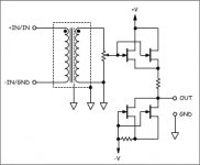
Are you set on going complimentary? If not, how 'bout a single-ended buffer? Transformer included out of habit. Omit.
Attachments
Charles Hansen said:
It depends on what you are trying to do. A cascode will offer two benefits:
- Elimination of Miller capacitance on the input device. (standard or folded cascode)
- Ability to use a low-voltage input device in a high voltage circuit. (standard cascode only)
Unless I really needed one or both of these advantages, I would keep the circuit simple and omit a cascode. If you need a cascode, you would probably want to try a couple of different configurations and see which works best in your application.
Best regards,
Charles Hansen
...and makes the device much more linear, right!
You seem to rely more on the "simple is beautiful", how about your commersial products, just of curiosity but if I understand your type of audio design philosophy, cascodes are very hard to find in your products, right?
Anyhow, the cascode question, you stated two things and I gave another one, but I guess I wondering about something elsethan these features with cascoding.
If I try to specify my question I guess that I'm asking what diffrent "characteristic" will a FET vs BJT as a cascode give harmonics/musically when used in the input stage as I noted JohnFerrer used cascode input with just FET's?
As I belive a BJT is quite "transparent" but with FET's I must admit I don't know...
Regards,
Michael
john curl said:Hi Charles, don't you think that a 30 ohm load would be a bit compromising for this simple complementary follower? Were you thinking about 600 ohms?
It is a shame that it is so difficult to get high current complementary jfets in a decent power package. This follower is just about perfect in most other ways.
Hello John,
Earlier in this thread John Ferrier had noted that he was using 300 ohm headphones. The output impedance of the circuit I drew is about 25 to 30 ohms. I've tried it before with headphones of several hundred ohms impedance using two 9V batteries for the supplies and it sounded quite good.
Is this the ultimate headphone amp? Probably not. It was just intended as a suggestion for a proven circuit to get John Ferrier started. The best way to learn is to try different things, but it's also nice to have a starting place.
I agree about the device selections that are available. It really is a shame, because I'm sure the entire audio community could make even better stuff if we could also design the semiconductors. It's nice that Semelab stepped in to fill the void left by Hitachi with their lateral power MOSFETs, and I'm glad that Toshiba is still making nice small-signal JFETs. But I could really use a few other nice parts....
Best regards,
Charles Hansen
johnferrier said:The headphones I have in mind are a 300 ohm load and the plan is to use four complementary JFET pairs in parallel (Idss matching amongst all pairs to < 2%). Should idle at just over 40mA per channel.
If your devices have an Idss of 10 mA and you skip the source resistors, the total output impedance will be around 3 or 4 ohms. Whether or not it will improve the sound can be quickly determined with a listening test. I would expect that it would, but have never tried it and don't know.
The difficulty with your approach will be to keep the DC offset to a reasonable level. If you have enough FETs you might be able to manage by simply matching all 8 parts together. But speaking from experience, this could be tricky to pull off.
Best regards,
Charles Hansen
Ultima Thule said:...and makes the device much more linear, right!
what diffrent "characteristic" will a FET vs BJT as a cascode give harmonics/musically when used in the input stage as I noted JohnFerrer used cascode input with just FET's?
As I belive a BJT is quite "transparent" but with FET's I must admit I don't know...
Hello Michael,
The cascode *doesn't* make the device more linear, in general. This is probably something that was written in a magazine article one time and has been repeated so much that people think that it's true. It makes a very low impedance load for the input device. This will essentially eliminate Miller capacitance, which can be a help at very high frequencies (usually well outside the audio band). Probably by "more linear", the original author meant "more extended frequency response".
To see the effect of the cascode at low frequencies, just take a plot of the devices characteristic curves. The cascode will make a very steep (low impedance) load line that will go almost straight up and down.
With regards to your specific question, I don't know the answer. The only time I've used a cascode was in our early designs where we used a folded cascode. Both the input and cascode were FETs. I have never tried a bipolar cascode.
Honestly I think that the audio community is only beginning to scratch the surface of what is possible. Each person only has a finite amount of time for trying new ideas. But with a community such as this, we can share our knowledge and make greater progress.
Best regards,
Charles Hansen
Hello Jam,
I'm glad you're enjoying this. I keep getting questions about cascodes, which is kind of funny because I really don't have much experience with them....
Assuming that you're talking about a conventional (non-folded) cascode, I have thought about this somewhat. The answer isn't completely clear, although you can see some advantages and some disadvantages on each side.
If you reference the source of the input device, then you are able to keep the applied voltage across it truly constant. This will minimize the Miller effect. Also, you are able to get a greater output voltage swing for a given supply rail in this way.
There are also some potential problems with this approach. One is that it may be more difficult to get a "clean" reference for the cascode (unless you happen to be using a JFET, in which case the biasing is trivial as seen in the schematics that JF posted). Another is that the source of the input device now has a load placed on it, so some energy is going off somewhere. Finally, any kind of "bootstrap" like this will have some time delays associated with it. So maybe for the cascode's behavior is slightly different for the first microsecond or so.
All that said, there are some big caveats to apply here. First of all, since there usually isn't that big of a signal at the source of the input device, there may not be much real difference between these two approaches. Second of all, I have never actually listened to a comparison of these two approaches. So all of my mental exercises are just that. Please let us know what you find out when you do the tests yourself!
Best regards,
Charles Hansen
Charles,
You bring up some thoughts I have not considered.........maybe cascodes for the input stage of your next design?
In my experiments a few years ago I found that hooking the bias element to ground always sound better than attaching it to the source even though the latter is supposed to be more linear and have lower distortion..................go figure.
Regards,
Jam
- Status
- This old topic is closed. If you want to reopen this topic, contact a moderator using the "Report Post" button.
- Home
- Amplifiers
- Solid State
- Another Zero Feedback Amplifier