Going back to my original comment, I would again encourage you to simplify, simplify, simplify.
You only need a gain of 16x, you said. You don't really need two gain stages to do that, one is plenty. So if you want to kill two birds with one stone, change the second stage into a common-gate stage and create a folded cascode. Now you don't need the separate cascode transistors for the first stage.
You only need a gain of 16x, you said. You don't really need two gain stages to do that, one is plenty. So if you want to kill two birds with one stone, change the second stage into a common-gate stage and create a folded cascode. Now you don't need the separate cascode transistors for the first stage.
GRollins said:Since, by definition, a typical feedback amp has scads of gain, I've always thought it likely that much of the improvement in sound quality in a "zero feedback" (semantics be damned...) amplifier was due to the fact that you weren't asking for as much gain. As such, the devices were more likely to stay in a relatively linear region.
Grey
This is interesting. With the Borbely Super Buffer, stage gains are as follows:
1st = 15X
2nd = 75X
3rd: 1X
Total gain: 1125X
Global feedback, of course, does not change the gain of any of the stages. It generates a difference signal at the input that is very small (basically, Vout / (1125 x GFB gain)). So, the input stage is working over a very small (and linear) range. With my redition of ZFB, the first stage works over a much larger range (~75X larger than orginal design).
JF
Looking at some different details of the circuit, you don't need C1 nor C5. The FETs themselves will have input capacitance that will create whatever poles you need. External capacitors will only color the sound.
Finally, you won't need R13 and C12 at the output. FETs don't suffer from the instability problems that plague bipolars. This is doubly true since R14 is buffering any potential capacitive loads.
Finally, you won't need R13 and C12 at the output. FETs don't suffer from the instability problems that plague bipolars. This is doubly true since R14 is buffering any potential capacitive loads.
Charles Hansen said:But the first stage won't have *any* gain to speak of. If we ignore the parallel transistors and the cascodes, consider that one transistor will be turning on as the other is turning off. Therefore the current through R3 and R4 will be essentially constant as the input signal changes.
What you need to do is run a resistor from the junction of R5 and R6 to ground. The gain for each half of the first stage will then be set by the formula:
Av = R3 / ((R5 + 1/gm) + (2 * Rnew))
In this case the transistors will be running at about 1 or 2 mA, so 1/gm will be around 100 ohms.
My apologies Charles. I threw that together quickly at work. I didn't have time to actually run simulation. What I was after was a gain of 5 in the first stage and a gain of 3 in the second. It was an attempt at something of substance rather than just making comments...
Thanks for taking time to look over the schematics : ).
JF
johnferrier said:What I was after was a gain of 5 in the first stage and a gain of 3 in the second.
OK, since my previous postings I've now seen your schematic of the original Borbely circuit. Now I can understand more where you were coming from and how you got there.
Starting with a circuit that was designed to have really high open-loop gain (1125x) so that a bunch of loop feedback could be used is not that great of an approach for making a zero feedback amplifier. (I'm going to repeat my previous recommendation more firmly now.) You really need to get rid of one of the gain stages.
The problem that you're going to run into by using two gain stages is that you can only kill gain in one of two ways:
1) Add more degeneration to the sources. This is OK, except that it also decreases the idle current at the same time. You then either have to use a current source in the sources or else go to *much* higher rail voltages. Otherwise the idle current in the devices will drop to very low levels. This latter point will be a problem because things will head towards class B instead of class A.
2) Lower the load on the drains. Again this will work, but you have two problems. The first is that the linearity suffers somewhat as the load decreases. But worse is that more idle current is required to keep the circuit in class A. And you've already reduced the idle current in step #1.
So you really need to work with the device and not try and force a square peg into a round hole. One way to think about this is to consider a vacuum tube line stage. The traditional two-triode circuit (Dynaco, Marantz, Audio Research, etc.) works well with feedback. But if you want a zero feedback linestage, trying to kill the gain from two stages is unproductive. There are lots of zero feedback tube linestages (Conrad-Johnson, etc.), and they all use a single triode.
So to save you a lot of trouble, I would suggest instead of starting with Borbely's circuit designed for feedback, to start with the MOSFET power amp circuit I posted in the other thread a few days ago. Replace all the MOSFETs with JFETs, throw away the current sources for the diff pairs (you don't need them with JFETs), and throw away half of the balanced bridge design (since headphones only work with a single-ended output). You only need 6 FETs total.
Enjoy,
Charles Hansen
Steve,
Perhaps I could try that (a single differential stage) too. (Anyone else, got something for me to try? hehehe...) Actually, to find my matched pairs, I've got extra JFETs, I guess it would be fun to try a few things before I make a final decision and finish this project. It will be sort of interesting to do listening tests, but....I think that it is pretty time consuming.
(And how did I know that Steve was going to post the following?)
Charles,
I'll assume you were referring to the Ayre V-3 schematic rather than the Patent you started this thread with. It's kind of late. I'll need to go through this later.
Thanks guys.
JF
Weird. My original post seemed to have disappeared. When I reposted it, it was still gone but there was your reply.
Anyway, what cans do you have? I notice you've got 300 ohms shown in your schematic. You using Sennhesiers? If so, I think Headroom sells a modified cable with separate connections for each speaker (intended for use in their topline headphone amp) using a four pin XLR I believe.
se
Anyway, what cans do you have? I notice you've got 300 ohms shown in your schematic. You using Sennhesiers? If so, I think Headroom sells a modified cable with separate connections for each speaker (intended for use in their topline headphone amp) using a four pin XLR I believe.
se
johnferrier said:(And how did I know that Steve was going to post the following?)
Dunno. I'm wondering if it had anything to do with that strange feeling I got right between my eyes just a moment ago?
")
se
Yep, I've got Sennheisers, which are probably the easiest to modify for differential/balanced signals. It's a matter of splicing in a second headphone plug at the end of the cable. Meaning, of course, the grounds are connected at the plug end. Anyways, I just received my second (and last for a while) shipment from Percy Audio. Going to have to wait before I purchase something like more plugs/sockets. You had recommended Percy. He does have a good selection, is timely (for me, much faster than your directionality cables), and has a sense of humor.
JF
JF
johnferrier said:Yep, I've got Sennheisers, which are probably the easiest to modify for differential/balanced signals. It's a matter of splicing in a second headphone plug at the end of the cable. Meaning, of course, the grounds are connected at the plug end.
Messy. I just checked HeadRoom and they don't sell the cable directly. But I'd recommend going that route instead of chopping up your exiting cable. I also seem to recall seeing somewhere someone selling the Sennheiser plugs which mate to the headphone end. That would allow you to make your own cables.
Anyways, I just received my second (and last for a while) shipment from Percy Audio. Going to have to wait before I purchase something like plugs/jacks. You had recommended Percy. He does have a good selection, is timely (for me, much faster than your directionality cables), and has a sense of humor.
Yeah, he's good people. Sometimes he gets a bit behind, but mostly he's right on top of things.
se
OK Jam.
John, here is one way to think about the folded cascode circuit. The gain of the first stage is (approximately) set by the ratio of the source resistor to the drain resistor.
But in the folded cascode, the drain resistor for the input stage is effectively the source resistance of the cascode transistor (1/gm). Or to look at it another way, the cascode is acting as a source follower to "nail down" the voltage at the drain of the input stage.
So if you are looking at it from a voltage gain standpoint, there is *negative* voltage gain from the first stage. All the voltage gain is happening from the second (cascode) stage. For the cascode stage, the gain is (approximately) set by the ratio of its drain and source resistors.
Another (and probably more useful) way to look at it is as follows. The input transistor is acting only as a voltage to current converter. The ratio of voltage to current is determined by (1/gm + Rsource). The cascode is acting as a "current conveyor", and sends that current to the drain resistor (load) of the cascode. The drain resistor acts as the current-to-voltage converter. So the gain of the composite stage is:
Av = Rdraincascode / (1/gm + Rsource)input
Hope this helps,
Charles Hansen
johnferrier said:Well for headphones, I'm thinking why not try buffering the attenuator with complementary source followers.
Why?
jam said:Hey! Let's get back to zero feedback designs .......................
Ok.
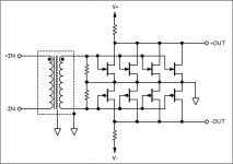
So, heading down the zero zero path, Charles encouraged John to simplify, simplify, simplify.
So let's pluck the cascodes and tweak the input a bit, and consider something along the lines of...
Attachments
Well, it takes me time to assimulate this information. But, kind of in the spirit of simplify, I dropped down to a single stage--the output. Obviously, it will have no gain. I'm not interested in loud listening levels. And this would be a way to try ZFB?
Converting the V-3 to JFETs looks like a two stage design that will take some time simulate. However, to tune the matches, I'll probably have the Borbely complementary circuit (four parallel pairs of 2sk170/2sj74s) on a breadboard this weekend.
JF
Converting the V-3 to JFETs looks like a two stage design that will take some time simulate. However, to tune the matches, I'll probably have the Borbely complementary circuit (four parallel pairs of 2sk170/2sj74s) on a breadboard this weekend.
JF
Charles Hansen said:OK Jam.
John, here is one way to think about the folded cascode circuit. The gain of the first stage is (approximately) set by the ratio of the source resistor to the drain resistor.
.
.
.
Another (and probably more useful) way to look at it is as follows. The input transistor is acting only as a voltage to current converter. The ratio of voltage to current is determined by (1/gm + Rsource). The cascode is acting as a "current conveyor", and sends that current to the drain resistor (load) of the cascode. The drain resistor acts as the current-to-voltage converter. So the gain of the composite stage is:
Av = Rdraincascode / (1/gm + Rsource)input
Hope this helps,
Charles Hansen
Good stuff. I'll review this and some of your other posts to better understand these topologies. Thanks!
JF
- Status
- This old topic is closed. If you want to reopen this topic, contact a moderator using the "Report Post" button.
- Home
- Amplifiers
- Solid State
- Another Zero Feedback Amplifier