Another Amp Built on a Metal Plate
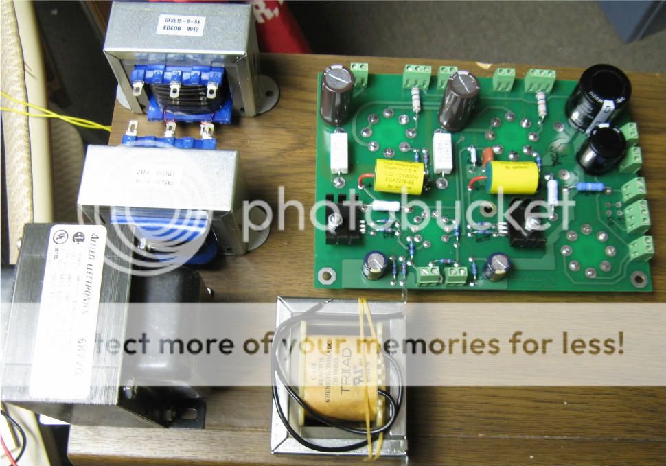
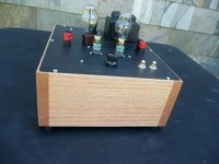
Here's a photo of a Direct-Coupled ("DC") Darling (with 1626s and 8352 drivers) built on a Hammond cover plate. The EDCOR 5K:8 ohm OPTs are underneath with the Allied filter choke (6H or 7H?).
The chassis base is some nice clear white oak that was left-over from furniture making. The grain is very nice. The joinery is ultra smple, just butted together and glued with Titebond II (stronger than the wood). Didn't even bother with dowels or biscuits, as any stress that would threaten the joints would certainly wreak havock with tubes, etc.
Let me know if you want to see the guts.
Attachments
DC Darling Guts
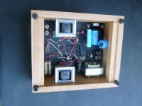
I realized that nobody here doesn't want to see GUTS, so while I'm in the directory already, here they are.
Note the battery bias for the 8532 (single triode) driver tubes.
I didn't have an appropriate bypass cap in stock, but I had plenty of AA cells and holders, so I tried battery bias. It's at least as good as the by-passed biased resistor(s); one thing I am thinking of trying is a "replacement cell" so I can compare the bypassed resistor to batt bias.
Imagine a dowel with copper wire end terminals with resistor and cap between. Pop-out the battery and pop-in the dowel/resistor/bypasscap. Should be able to get a quick comparison without that pesky time lag.
Gotta noodle on that. Maybe brass round-head screws (or even upholstery tacks!) holding down ground tabs; solder between the tabs.
Attachments
I build another SimpleSE. I don't know why, when I check the B+,
I have 380 Volts. I hoped to have 430 to 450 Volts. I change the 5AR4. The B+ is 380 volts again. I check the soldering of the 5AR4'S socket .
What could be the cause of the problem ? A bad capacitor ? A bad soldering ? Where to begin my research?
Power transformer: James JS-9611 (360-0-360)
OPT: James JS-6123HS
B+ Issues
Tigrine, what power tubes are you using?
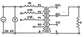
How is the OPT wired? that is, which primary leads, which secondary leads, what speaker load? (by "leads", I guess I mean "tabs" on the James transformers).
For example, 5K primary, 8ohm secondary, 8 ohm speaker.
I ask because I've used James OPTs with a secondary-to-load mismatch on purpose.
Generally, rectifier tubes either work or they don't (i.e. internal lightning). The fact that you're getting a B+ voltage means that it isn't a rectifier or socket problem. I suspect a larger load than you anticipated.
Tigrine, what power tubes are you using?
How is the OPT wired? that is, which primary leads, which secondary leads, what speaker load? (by "leads", I guess I mean "tabs" on the James transformers).
For example, 5K primary, 8ohm secondary, 8 ohm speaker.
I ask because I've used James OPTs with a secondary-to-load mismatch on purpose.
Generally, rectifier tubes either work or they don't (i.e. internal lightning). The fact that you're getting a B+ voltage means that it isn't a rectifier or socket problem. I suspect a larger load than you anticipated.
B+ Issues, continued
What power tubes, then?
What's the specs on the choke, i.e. impedance (Henries, H) and DC Resistance (DCR, in ohms)?
Have you run a simulation of the power supply on, for example the PSUD program from Duncan Amps?
I'm guessing (just a guess) that your choke may be high DCR (e.g. 300-500 ohms), and maybe also you have high plate current, sucking down the B+. Just a guess at this point.
B+ Issues, continued
I've used that exact choke on a SimpleSE, and don't remember such a voltage drop with a 5AR4 rectifier.
Suggest you run the PSUD power supply software from the Duncan Amps site. I would do it for you, but I'm at work. Maybe tonite.
A couple of additional questions:
(1) Do you have the solid state rectifiers installed? The FREDs, I mean? If so, it's a simple matter to add a jumper wire (see the schematic & wiring diagrams to use the S/S rectifiers, which will give you the very lowest voltage drop possible and therefore the highest B+. That SHOULD give you say 420VDC B+.
(2) Just to confirm, you DID say you were using a 5AR4 rectifier (AKA GZ34), right? NOT the 5R4G (whatever variety)?
I ask because the 5R4 and its cousins have a very high voltage drop; note that I often fire-up an amp with a 5R4 rectifier, then change rectifiers to get the best-sounding B+. With the SimpleSE, that's usually the HIGHEST B+, unless using 6V6s or similar such as 6BQ6 with the top cap.
(3) Did you measure the high voltage coming out of the power transformer? ie EACH red wire to ground? Is it really 360-0-360VAC? [don't try to measure between the red wires, as you might fry your meter if it isn't autoranging or if it doesn't go high enough. Do not ask how I know that.]
Normally in North America the high voltage is HIGHER than the transformer spec, not lower, as the AC supply voltage usually runs high (mine runs about 116 to 122 VAC)
(4) What's the plate current you're running through those KT88s?
That is, the voltage on the cathode divided by the bias resistance.
B+ issues, continued some more
I've got your P/S modeled in PSUD, as follows:
360-0-360 high voltage
5AR4 rectifier
47uF first cap
5H, 64 ohm Hammond choke
120uF 2nd cap
(for now, I left off the supplemental cap; that will load the rectifier but not lower B+)
5K Load
As you said, with these conditions you SHOULD be getting something on the order of 435VDC, more or less.
With a 150mA constant current load instead of the 5K resistive load, the B+ does drop to about 405 VDC. However 150mA seems quite high, and you have 380VDC.
With a 5R4GYB rectifier AND ~105mA constant current draw, I DO get about 380V B+.
Alternately, I can get 380 VDC with a very small first cap (e.g. 2uF, almost choke input territory).
Can you check your measurements, especially
High voltage IN
first cap value
power tube plate current
B+ at the OPT (NOT the voltage on the plate side which will be 10-20 V lower)
Also make sure that the high voltage center tap is properly grounded to the board
My P/S modeled in PSUD, as follows:
360-0-360 high voltage
5AR4 rectifier
47uF first cap
5H, 64 ohm Hammond choke
120 uF 2nd cap
5K Load
80 uF for the supplemental capacitor to the power supply
(1) No solid state rectifiers (Fred)
(2) I try 5AR4 from Shuguang and 5AR4 (NOS) from Philips
(3) The high voltage coming out of the power transformer is really 360-0-360VAC. The AC supply voltage runs 120 to 122 VAC.
(4) I will check the measurements of the plate current through the KT88
and the B+ at the OPT tonight.
Thanks Hareynolds for your help.
There are the measurements I took.
For each GEKT-88
pin1: 43 volts
pin2: 28 volts
pin3: 442 volts
pin4: 440 volts
pin5: 0,18 volts
pin6:-
pin7:-
pin8: 43
For the 5AR4 Shuguang
pin2: 459
pin4:-
pin6:-
pin8: 43
For 12AT7 JanPhilips
pin1: 237 volts
pin2:-
pin3: 1 volt
pin4: 28 volts
pin5: 28 volts
pin6: 222 volts
pin7:-
pin8: 1.95 volts
pin9: -
T2-PRI (T3-PRI has the same measurements)
1: 443 volts
2: 442 volts
3: 449 volts
tigrine said:I build another SimpleSE. I don't know why, when I check the B+,
I have 380 Volts. I hoped to have 430 to 450 Volts.
Uh, where's the problem? You say you have 442 volts on the plate. Isn't that between the 430 and 450 you wanted?
B+ issues, finis
I agree with Ty
The only "problems" I see are some confused numbers, e.g.
the voltage at terminal #2 on the OPT should be BETWEEN the voltages of terminal #1 and #3 (as terminal #2 is the ultralinear tap). Let's chalk that one up to "rounding error" or perhaps transposed numbers.
the elevated filament voltage (~28 volts) should be present at pins #2 and #7 on the KT88s and pins 4,5 and 9 on the 12AT7. Again, probably transcription error not a problem if everything's glowing.
SO, WHERE EXACTLY did the 380V measurement come from?
Just curious, as it looks like this amp is spot-on.
So what's the bias resistor? Assuming 560 ohms (a typical SimpleSE starting point), the plate current is 43/560=~0.077A or 77 mA. Plate dissipation is ~30.7 Watts, versus a "design max" of 35W, so you're good.
Most important, how does it sound? Once the power tubes break-in after a few hours, it should sound terrific.
tigrine said:Yes, my bias resistor is 560 oms.
I measured the 380 volts to T1-Red.
Simple answer, that's not B+.
")
tigrine said:Thanks for your help. I have a lot to learn.
The newbie.
No worries, I'm a relative newbie too. What you are measuring at the T1 RED terminal is the AC output of your transformer, before rectification and smoothing (unless I'm mis-remembering).
Alright I am making some headway on the chassis. I built the main structure out of wood and box jointed the corners. Turned out pretty good considering it was the first time I attempted a box joint with a homemade jig. For the top plate I sourced some anodized aluminum at a commercial window shop we do business with. I just need to stop in and tell them what size I am looking for. I am just gathering a couple more parts for the final build. I am thinking of using an inrush current limiter on the main power line and also was wondering if adding a bleeder resistor of around 2watt 220k ohm on the 80uf 370v motor run capacitor would be smart?
The newbie again
Let me know if I'm right.
Here the connections that I made:
1) The negative (black) binding post and the 8 ohms (of the 6123HS OPT) are connected to ground on the board (T2-SEC-1)
2) The positive (red) binding post and the 0 ohms (of the 6123HS OPT)are connected to cathode feedback (T2-SEC-2)
Let me know if I'm right.
Here the connections that I made:
1) The negative (black) binding post and the 8 ohms (of the 6123HS OPT) are connected to ground on the board (T2-SEC-1)
2) The positive (red) binding post and the 0 ohms (of the 6123HS OPT)are connected to cathode feedback (T2-SEC-2)
Attachments
- Status
- This old topic is closed. If you want to reopen this topic, contact a moderator using the "Report Post" button.
- Home
- More Vendors...
- Tubelab
- Another TubeLab SimpleSE Build