FWIW on Binding Posts
I've always had trepidations about screw terminals for high voltage, but they've seemed to work pretty well on the Simple SE board, provided you don't overtorque them; I try to grab the plastic ones with thumb and forefinger while cinching-down on wires to avoid unnecessary torque getting translated to the pins.
The Mouser single-pins, strangely enough, are lots stronger in torque, since you flow solder under the entire base, making a pretty strong joint (nearly pure shear in torsion, rather than the bending-and-shear of the pins on the plastic ones).
I use the single-pins only on the bias resistors, as I am ecstatic about the CHEAP Russkie PIO caps that I've been using. I've used Jensens and Auricaps on DHT SE amps before, and they are quite nice and transparent, but bang-for-the-buck I haven't seen anything better than the green Russian caps. Can't see any reason not to use the single-pins there, too, however.
On the bias resistors I make L-shaped bends in the leads in ONE direction, and slip the leads into the screw terminals TOWARDS the caps. To change, loosen screws, slip out old ones, slip in new ones.
Note that I have always assumed that if wanted to make this joint semipermanent, I could drop a little solder inside the screw terminal.
BTW my very first tube amp was an EL34 triode-strapped SE. I tried all manner of permutations, but never really liked the sound. There wasn't anything WRONG, exactly, just not my cup of tea. More like green tea than my favored Hong Cha with Hot Milk; just not rich enough somehow. Far prefer a DHT or even one of my Darling amps (pick your flavor, they're all sweet). Again tried some of those E. German "Seimens" tubes in my first Simple SE, ultralinear, tirode, still didn't like the sound. Sold that amp with the EL-34s in.
Well I have made some progress in the past few days. I got all the resistors on the board except for R2 which is on the way. I have soldered on the Auricaps, the leads barely fit through the holes but I managed to get them through. I am waiting on the sockets so that I can get those soldered up and then finish off the board. Also Edcor just shipped my transformers out that is pretty much that last piece that I will be waiting on for the amp. Now I just need to design a chassis to house it. I was planning on an all wood structure as I don't have a whole lot of access to metal working tools but I do have a full wood shop at my disposal. I also ordered up these switches for it:
SPST Toggle Switch
DPDT Toggle Switch
Pictures to come this weekend")
SPST Toggle Switch
DPDT Toggle Switch
Pictures to come this weekend
Just a quick question. How do you all tie in your grounds. I was thinking a terminal strip and then daisy chain the backside leading to the ground terminal on my IEC socket. Also on Georges site he says to ground the capacitor case....well to be honest not sure how that is done with my large motor run capacitor. Would I attach the ground to my mounting bracket for the capacitor? I plan to have my motor run cap poking through the top of the chassis. Also my chassis is going to be entirely made out of wood. Not sure if I had mentioned that or not.
On another note...got the board all soldered up. Dont have the output transformers yet. I wanted to design the layout but I really wanted to wait until I have those in hand.
On another note...got the board all soldered up. Dont have the output transformers yet. I wanted to design the layout but I really wanted to wait until I have those in hand.
A "star ground" pattern is what you want. A terminal strip like you are planning would be close, but the best thing is to solder each ground to a set of eyelets (each can contain as many as can fit or is convenient) and the bolt them all to the chassis with the same screw. The ground from the EIC can ground here too, but it's not necessary.
The motor run would be grounded via the capacitor mounting bracket, though the ones I have are anodized aluminum, so that won't work either without removing the coating.
Russ
The motor run would be grounded via the capacitor mounting bracket, though the ones I have are anodized aluminum, so that won't work either without removing the coating.
Russ
Grounding the Simple SE -PLUS- 6BQ6s in Simple SE
I typically use Star grounding on tube amps. What you're trying to avoid is a ground-loop, where a bad ground across the chassis grounds somethng important, like the input phono plugs (i.e. USE INSULATED PHONO PLUGS) or say the cathode bias ground for the driver tubes.
On the Simple SE, I generally follow George's instructions, as follows:
(1) ONE single ground to the chassis, typically at one corner of the power transformer. Be sure to scrape paint off of both sides of chassis and a contacting part of the power trans. I use the cheap plated ground tabs (they're a few cents each from DigiKey I think).
ANY exposed metal bits should be grounded to the chassis this way (e.g. top-mounted chokes or OPTs). An ohmmeter between a transformer body and the chassis ground should show <<1 ohm.
(2) attach the GREEN ground wire from the AC power cord
(3) DON'T attach the chassis gorund directly to the Power Center Tap screw terminal on the Simple SE board (where the Red/Yellow wire goes; there are normally TWO terminals). Note however that I usually also attach a looped piece of tinned copper wire there too, as an easy place to attach a ground wire for the meters.
(4) run a separate wire DIRECTLY from the input phono plugs. I use a black 22 or 24 gauge stranded wire; just loop it around the board.
This wire SHOULDN'T be carrying any amperage, just stray voltages.
One advantage of the Simple SE set-up is that the board ground LITERALLY (as well as figuratively) FLOATS above the chassis, grounded to the chassis ONLY at the inputs. No loops, absolutely quiet (that is, no hum).
On a SEPARATE NOTE has anybody tried 6AQ6s in the Simple SE board (the ones wth the top caps)? I finally got some 6AQ6GAs dialed-in nicely ont he SimpleSE board, as follows:
Allied 6K56VG PST (270-0-270, 120 mA)
Allied 7H? 150 mA 150 ohm (IIRC) open frame choke
5R4GYB rectifier (for LOWEST B+, to keep the screen down in uLin)
EDCOR 10W 8K:8ohm OPTs (the little ones; I had them on-hand)
~750 ohm bias resistors.
NO cathode feedback (curiously, sounds better w/o it; high Rp maybe?)
I get B+ around 275V, I think, and 52 mA plate current (around 40V at the cathodes). In Ultralinear, the grids are nice and toasty (about 240V? instead of the data sheet max of 150V) but these puppies sound fantastic. Plate dissipation is what, just over 12 Watts, so I'm only cooking the screens, not the plates. Wow wow wow.
The Biggest Bottle ones (with the 6AV5-looking plate structure) sound a little better than the mere GAs (and draw more plate current, too), but the mere 6BQ6GAs sound fantastic too, esp. after a few hours "descaling"at operating conditions. These tubes are STILL cheap cheap, and unlikely to get expensive as there are TONS of them, and most folks (e.g. my 23 year old) don't want a plate cap around tempting the curious and/or inebriated. The detail reminds me of my 71A monoblocks, except the 6BQ6s seem more lively and "brighter".
Anybody else tried this? What op conditions? what OPTs?
Thank you everyone for the replys. One thing though, since I am using a non metal case(wood) wouldnt everything need to be brought into the ground of the IEC outlet.

Something like this which is in George's diagrams. Also all metallic objects such as transformer cases etc would be tied in too. Also it seems that only one input jack needs to be grounded. I have seen different else where on the web while looking at different amps.
Something like this which is in George's diagrams. Also all metallic objects such as transformer cases etc would be tied in too. Also it seems that only one input jack needs to be grounded. I have seen different else where on the web while looking at different amps.
Grounding Wood
Yes. Might use a wood screw x machine screw thingy as a ground point. I think they have those in the drawers at Home Depot or Lowes.
Alternately a terminal strip screwed to the wood next to the IEC would work.
The IEC gorund terminal itself will work, just be extra careful about too much heat on the terminals, as they melt quite easily (think they're HDPE).
Remember to separately ground the transformer cases, no joke, espe if using older iron.
Using IEC connector pin for ground
Yup, good idea to use the old IEC cable to steady the pins; that will also serve as a heat sink to keep the temp of the pins lower.
I try to solder to those IEC pins just once, and quickly. Bend all the wires on there (like it says in the old Heathkit instructions), then clean and tin your iron tip, and just touch it to the pin until the solder flows, then pull off.
Re: Grounding Wood
Yep I plan to have every metallic object that could possibly be touched ground. I figure especially with my case being all wood I need to take extra precaution. I was even thinking that a ring connector around the switch mounting pole might be beneficial in case of a faulty switch. I figured the IEC would melt if I decided to solder to it so I think I am going to utilize a bolt to bring all my grounds some what of a star ground. I have decided to mount the motor run under the chassis which will keep any potential problem that it may cause out of the reach of hands...at least until the case is opened and in that case the power will be disconnected from the amplifier.hareynolds said:Yes. Might use a wood screw x machine screw thingy as a ground point. I think they have those in the drawers at Home Depot or Lowes.
Alternately a terminal strip screwed to the wood next to the IEC would work.
The IEC gorund terminal itself will work, just be extra careful about too much heat on the terminals, as they melt quite easily (think they're HDPE).
Remember to separately ground the transformer cases, no joke, espe if using older iron.
Thanks for the tip. It is nice finding out little things to make the installation go smoother.rknize said:Put an old computer cable in the EIC connector to keep the pins steady.
Wood/Steel Chassis
I used to use Hammond steel or aluminum chassis, but found that it was difficult to get a high WAF (wife acceptance factor) with a naked chassis, so I have taken to splitting the difference:
I now use steel Hammond cover plates (the black powder coated ones, in order to save a step) mounted on top of solid wood chassis. This works esp. well with the EDCOR OPTs which aren't very presentable, so need to go under the chassis.
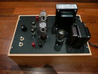
Here's a Darling amp on a maple base, for example.
(this one's on email right now; search "darling amp" for more photos)
This works really well, as (a) you have your steel chassis to ground-to (b) the plates are pretty cheap, so if you screw-up it isn't tragic, and (c) the system is pretty flexible; I have made one amp with different plates for Power Supply, amplifier section and OPTs, so I can pop different "modules" in and out at will. I use terminal strips like George at tubelab to join the modules together.
The only downside is that you lose about 3/8" all the way round, but I think the advantages make up for the loss of real estate; besides, you're not limited to 2" or 3" deep any more.
I used to use Hammond steel or aluminum chassis, but found that it was difficult to get a high WAF (wife acceptance factor) with a naked chassis, so I have taken to splitting the difference:
I now use steel Hammond cover plates (the black powder coated ones, in order to save a step) mounted on top of solid wood chassis. This works esp. well with the EDCOR OPTs which aren't very presentable, so need to go under the chassis.
Here's a Darling amp on a maple base, for example.
(this one's on email right now; search "darling amp" for more photos)
This works really well, as (a) you have your steel chassis to ground-to (b) the plates are pretty cheap, so if you screw-up it isn't tragic, and (c) the system is pretty flexible; I have made one amp with different plates for Power Supply, amplifier section and OPTs, so I can pop different "modules" in and out at will. I use terminal strips like George at tubelab to join the modules together.
The only downside is that you lose about 3/8" all the way round, but I think the advantages make up for the loss of real estate; besides, you're not limited to 2" or 3" deep any more.
Attachments
eBay, not email
I must be tired.
I have used this technique for the first two Simple SE boards I did; use the 17 x 10 inch Hammond cover plate.
Note that if you use heavy iron, you will need to stiffen the cover plate some. You can use 1"x 1" angle from Home Depot, or say a 1" wooden cross brace (although that eats up volume).
I used the 1x1 angle as a transverse brace under the iron, and secured it with the PST & choke mounting bolts.
This gives quite a large SimpleSE amp, but there's lots of room to mount EDCORS upside down underneath, plus room topsides to convert to Transcendars or James or OneElectron OPTs if you later feel the desire.
Re: Grounding Wood
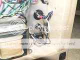
Another option is to crimp spade lug connectors onto the end of the power wiring, and just attach it to the spades on the back of the IEC. Please forgive the lack of connection to the ground lug of the IEC - this photo might have been taken during a state of "not quite done yet".
I agree with hareynolds, a metal plate on top of a wooden box is a very effective method for constructing an amplifier chassis.
hareynolds said:The IEC ground terminal itself will work, just be extra careful about too much heat on the terminals, as they melt quite easily (think they're HDPE).
Another option is to crimp spade lug connectors onto the end of the power wiring, and just attach it to the spades on the back of the IEC. Please forgive the lack of connection to the ground lug of the IEC - this photo might have been taken during a state of "not quite done yet".

I agree with hareynolds, a metal plate on top of a wooden box is a very effective method for constructing an amplifier chassis.
Re: Re: Grounding Wood
I guess the main reason I was going for a enclosure made entirely out of wood is due to cost saving measures and also that I have no metal working tools such as punches etc. I have pretty much an unlimited supply of wood at my disposal. So on that note if I were to do an all wood chassis I would just have to make sure to properly ground everything, switches, volume pot chassis, transformers, rca jacks, negative speaker terminals, any metal touchable objects. I am not objecting to a metal top plate I would just have to find someone that has the tools I could borrow to get the wholes punched.
Good call on the crimp on the female disconnects, I planned on picking up some insulated ones to connect to the IEC.Ty_Bower said:
Another option is to crimp spade lug connectors onto the end of the power wiring, and just attach it to the spades on the back of the IEC. Please forgive the lack of connection to the ground lug of the IEC - this photo might have been taken during a state of "not quite done yet".
I agree with hareynolds, a metal plate on top of a wooden box is a very effective method for constructing an amplifier chassis.
I guess the main reason I was going for a enclosure made entirely out of wood is due to cost saving measures and also that I have no metal working tools such as punches etc. I have pretty much an unlimited supply of wood at my disposal. So on that note if I were to do an all wood chassis I would just have to make sure to properly ground everything, switches, volume pot chassis, transformers, rca jacks, negative speaker terminals, any metal touchable objects. I am not objecting to a metal top plate I would just have to find someone that has the tools I could borrow to get the wholes punched.
Aluminum cuts straight with a circular saw, and holes can be made easily with an electric hand drill. A cheap step bit works wonders for the bigger holes. Measure carefully, and make printed templates on paper. Tape the template to the top of the aluminum, and drill right through. Always drill a small pilot hole before making larger holes.
Of course, an all wood deck works fine too. It's been done with success by others. Some have suggested "laminating" several thinner sheets of wood together with glue to make a stronger top plate.

Of course, an all wood deck works fine too. It's been done with success by others. Some have suggested "laminating" several thinner sheets of wood together with glue to make a stronger top plate.


If you have a drill press and you can mount the plate firmly, you can make very clean holes with hole saws. Aluminum is easy with cheap ones, but you can get through steel with the more expensive hardened ones if you run the drill at the slowest speed and use oil. I have even drilled through thin aluminum with those flat wood drill bits, though don't use your good ones. Hole saws with a hand drill is tougher, especially big holes. I have done it for computer fans and such, but I didn't really care if they were ugly.
As for step bits...they work OK as long as you don't get the single-sided ones. Get the ones with two cutting edges, not one. The single-sided ones will wander a bit as you step-up and the holes will slowly drift out of position, depending how you hold the drill. Going slow and using some cutting oil will help keep them centered.
As for step bits...they work OK as long as you don't get the single-sided ones. Get the ones with two cutting edges, not one. The single-sided ones will wander a bit as you step-up and the holes will slowly drift out of position, depending how you hold the drill. Going slow and using some cutting oil will help keep them centered.
Aluminum
I'm not a big fan of aluminum beacuse of (a) low modulus and (b) getting paint or powder coat to stick.
HOWEVER, one neat trick is to go to a sign supply company; sign companies use PRIMED aluminum sheets, usually with one side covered with a plastic film (the "good" side. That stuff paints pretty well, and the sign companies usually will shear it to size for you for cheap.
Strongly suggest getting two cheap tools when working with metal, esp. aluminum: (a) center punch (about $3 at Harbor Freight) and (b) deburring tool (about $5 with replaceable blades at any tool store).
Center punch ALL holes to prevent the drillbit from "skating". Less of a problem with Al, but still good idea. Deburring tool removes the burrs left from drilling.
Eventually, you should start collecting Greenlee chassis punches; they are really expensive, but worth every penny. Make clean holes (little deburring) every time, super fast, super clean. Don't fall for the "knockout" punches, they make holes that are exactly the wrong size for electrical stuff.
Well I think you have all convinced me to go with a metallic top. A-it will be easier for ground B-it looks better
I do have access to a bunch of vintage train/road signs maybe I will use one of them or else run out to my friends welding shop and see what he has laying around. That is the great thing about coming from a small town, it seems everyone and their brother has either a welder or some sort of metal shop. With the metal top I can use star grounding and have a studier top plate compared to what I could probably do with wood. The only thing I would probably have mounted to the front wood panel would be the potentiometer.
With the wood I was going to use solid 1/2 inch on the top and then chamfer with a router the tube holes to give them some breathing room and expose them a bit more. I will have to do some looking for some metal. I know of a few places that fab farming equipment that I know will do work off the clock for friends. Thank you everyone for the replys and help.
- Status
- This old topic is closed. If you want to reopen this topic, contact a moderator using the "Report Post" button.
- Home
- More Vendors...
- Tubelab
- Another TubeLab SimpleSE Build