Since loudspeakers (ESL or dynamic) are minimum phase devices at low frequencies, if you adjust the overall input-to-output response with equalization, the output acoustic impulse response is changed(improved) as well. One of the few times you get to feel like you are cheating the laws of physicsIs not the impulse response of the woofer unchanged?
")
BTW, this is not the case for attempts to fix room resonances with equalization though. Since the loudspeaker-room generally exhibits non-minimum phase behavior, decay time of room resonances is not improved with EQ.
You got itI'm trying to figure what the value of the pc (acoustic resistance of air) would be? I would hazard a guess that it is the speed of sound in air @ 20C = 343.21 m/s * the density of air 1.2041 kg/m3 which equals 413.25???? Am I way off base?

Note that this is the “specific acoustic resistance”, that is acoustic resistance per square meter. The MKS unit is Rayl. Properties of different acoustic elements are usually specified as “specific” impedances since the value doesn’t change with dimensions. For the same reason, acoustic calculations are generally performed using “specific” impedances...it's just easier.
Thanks Bolserst for #81. So there is a free lunch after all... Gosh, I've known about this for a long time, but never really understood it. KEF applied this technique at the other end of the spectrum (in about 1974) to a T27 tweeter, the result being an "acoustic Butterworth" circuit which gave the "ab" suffix to the Reference 104ab speaker. Now I must go away and read up on this.
The hints and links in this thread have led me to an earlier post which I think it could be helpful to repeat here.
Although a common practice in the construction of ESLs has been to reduce the bass resonance to a Q of about 2 with damping (e.g. silk screen, as described and measured by Bolserst) Capaciti's post (#11 in the 2007 thread http://www.diyaudio.com/forums/planars-exotics/113094-building-question-panel-matching-2.html ) indicated that "if the tensioning procedure is at its optimized level, fundamental resonance show Q-factor lower than 1,5". I have not yet read elsewhere of this possibility with ESL diaphragms.
Following Bolserst's #65 I am now able to pose two other questions which were prompted by Golfnut's design.
1. I have no expereience of listening to a line source presenting a stereo recording, only an open baffle dipole (with conventional electromagnetic drivers). Bolserst's ESL line source simulator software enables me to understand where the near/far field transition frequencies are for any given size of ESL panel. Is it possible to describe with words how the difference might be perceived for a 1.2m x 20cm (47" x 8") or a 1.8m x 20cm (71" x 8") line source? (listening distance 2.2m, say 7')
2. Through the use of my Spendor BC1 speakers which were equipped by the manufacturer with small open stands (23cm / 9") to alter floor reflection I have been able to appreciate the significance of floor bounce on the sound, which can introduce a substantial dip in the response. (I am familiar with floor reflection calculations using height of source, height of listening position and distance to source) One sees that ESLs are often placed directly on the floor. When a line source is shorter than the floor to ceiling distance (say 1.2-1.8m ESL panel size for a 2.7m / 9' high room) what is the effect to be expected (if any) by raising the ESL from the floor?
Although a common practice in the construction of ESLs has been to reduce the bass resonance to a Q of about 2 with damping (e.g. silk screen, as described and measured by Bolserst) Capaciti's post (#11 in the 2007 thread http://www.diyaudio.com/forums/planars-exotics/113094-building-question-panel-matching-2.html ) indicated that "if the tensioning procedure is at its optimized level, fundamental resonance show Q-factor lower than 1,5". I have not yet read elsewhere of this possibility with ESL diaphragms.
The Q of the naked diaphragm resonance is determined by three factors (the real part of the radiation impedance (R) the imaginary part of the radiation impedance (2.pi.f.M) and the resonant frequency fo, hence Q = 2.pi.fo.L/R. For a given line source, the Q increases as 1/fo^2. So higher tension raises the resonant frequency and lowers Q. The damping cloth adds to the resistance, also lowering the Q.
BTW - the cloth should probably not be silk - monofilament mesh like screen printed cloth has better controlled - more uniform - resistance.
1. I have no expereience of listening to a line source presenting a stereo recording, only an open baffle dipole (with conventional electromagnetic drivers). Bolserst's ESL line source simulator software enables me to understand where the near/far field transition frequencies are for any given size of ESL panel. Is it possible to describe with words how the difference might be perceived for a 1.2m x 20cm (47" x 8") or a 1.8m x 20cm (71" x 8") line source? (listening distance 2.2m, say 7')
2. Through the use of my Spendor BC1 speakers which were equipped by the manufacturer with small open stands (23cm / 9") to alter floor reflection I have been able to appreciate the significance of floor bounce on the sound, which can introduce a substantial dip in the response. (I am familiar with floor reflection calculations using height of source, height of listening position and distance to source) One sees that ESLs are often placed directly on the floor. When a line source is shorter than the floor to ceiling distance (say 1.2-1.8m ESL panel size for a 2.7m / 9' high room) what is the effect to be expected (if any) by raising the ESL from the floor?
The effects are hellish complicated, not easy to predict. Imagine that the floor and ceiling are mirrors and you can see reflections of the ESL disappearing off in the distance. For a floor to ceiling ESL, the reflections form an infinitely tall line source and the behaviour is near ideal. If its not floor-to-ceiling then it behaves like an infinite line source with gaps at regular intervals. The result is a very complicated diffraction pattern that is fractal because the listener is in the near field (see Fresnel diffraction and Talbot carpet in wikipedia). It will have bumps and hollows all over the place at long wavelengths. But the amplitude of the bumps and hollows decreases as the height of the ESL increases (closer to floor to ceiling) - so taller is better. I've not looked at what happens with raising ESL off the floor but no doubt still complicated.
Capaciti's approach was apparently to LOWER the diaphragm tension (below that normally achieved with mechanical tensioning): "I guess you tension the membran mechanically. You should not. imo a heavily streched membran do not sound best...Better just to make thermal tensioning. Glue the membran with lowest tension to the frame. The tension should be just as high that major wrinkles are reduced." (post #8 http://www.diyaudio.com/forums/plan...ioning-vs-silicon-dots-resonance-control.html )
"silk screen" This is only meant in the colloquial sense in which the term is usually used: a fine mesh, usually of synthetic fibres, as examined and tested by Bolserst in 2009 (post #25 in http://www.diyaudio.com/forums/plan...con-dots-resonance-control-3.html#post1958582 )
"silk screen" This is only meant in the colloquial sense in which the term is usually used: a fine mesh, usually of synthetic fibres, as examined and tested by Bolserst in 2009 (post #25 in http://www.diyaudio.com/forums/plan...con-dots-resonance-control-3.html#post1958582 )
I've run into a bug when trying to embed a link so I'll resort to the old school approach. I wanted to point to an old thread that might still have some relevance to this discussion of panel resonances.
http://www.diyaudio.com/forums/planars-exotics/157388-anyone-built-roger-sanders-designs-4.html
My own recent measurements of large-ish DIY planar magnetic drivers reinforce the idea that common explanations of hashy CSD measurements of panel speakers are likely off the mark. I hope to have some cleaner measurements ready to share soon.
Few
After achieving a low diaphragm tension, silicone dot spacers were applied every few cm.Capaciti's approach was apparently to LOWER the diaphragm tension...
Without them, the low tension would result in the diaphragm collapsing to the stator wires when bias voltage was applied.
Attachments
Hi Bolserst: You have addressed something which I have not yet understood. Are these silicone dots in contact with the diaphragm in its central position, or do they simply act as "buffers" to limit the maximum excursion of the diaphragm?
Is this photo in fact one of Capaciti's ESLs? I have seen a reference of yours earlier to a photo of his ESL building, but had not been able to trace the source.
Is this photo in fact one of Capaciti's ESLs? I have seen a reference of yours earlier to a photo of his ESL building, but had not been able to trace the source.
The capacitive coupling between segments has been referred to earlier in this (and other) threads. Would there be any useful result if one were to space the segments further apart (e.g. leave out one wire between segments) so as to reduce the coupling? Or would this strategem alone not be suffcient to reduce the coupling?
The silicone dots hold the diaphragm in it's central position.
The Audiostatic patent on this method posted here:
http://www.diyaudio.com/forums/planars-exotics/283016-unknown-audiostatic-esl-2.html#post4544152
A pic of one of my early segmented panels before attaching the front stator showing two rows of silicon dots.
http://www.diyaudio.com/forums/planars-exotics/109789-esl-diaphragm-coating-20.html#post1942380
Yes, that is a pic of one of Capaciti's ESLs.
He used to have a website with many additional pics of the stators in various states of build and testing, but it is no longer active.
*http://www.capaciti.eu*
I remember one pic with stator laying outside in the snow to verify that temperature extremes would not harm the materials.
I tested this method, and leaving out one wire between sections reduced capacitive coupling by about 30%.The capacitive coupling between segments has been referred to earlier in this (and other) threads. Would there be any useful result if one were to space the segments further apart (e.g. leave out one wire between segments) so as to reduce the coupling? Or would this strategem alone not be suffcient to reduce the coupling?
If the wire was left in place, but grounded, the capacitive coupling was reduced by about 90%.
However, there were issues with corona generation with the grounded wire.
Capacitive coupling between sections isn't as big an issue as I had originally thought it might be.
It is only a problem on the first few segments when high value ladder resistors are used.
As long as D/S isn't set unusually large, or fL set unusually low the detrimental effect of capacitive coupling on polar response is very minor.
Found pics on another site at bottom of page here:Yes, that is a pic of one of Capaciti's ESLs.
He used to have a website with many additional pics of the stators in various states of build and testing, but it is no longer active.
*http://www.capaciti.eu*
I remember one pic with stator laying outside in the snow to verify that temperature extremes would not harm the materials.
Made in Germany
Snow pics here:
Qualität unserer Produkte
Thanks Bolserst for #91-#93. The details on stray capacitance are most instructive.
Presumably one has to place silicone dots between the electrically defined segments. Of course, not all of the ESL panels which had silicone dots would have been electrically segmented.
I used the wayback machine to search for the capaciti website you cited: https://web.archive.org/web/20100110062405/http://www.capaciti.eu/
One can still access the text, which gives many technical details, but I couldn't find any photos archived there.
Bolsert, Thanks for #91 which clarifies that the silicon dots trap the diaphragm at that point, preventing vibration. That being so, one can understand that the Audiostatic patent system of dots, (three down the middle which you linked to), will effectively divide the diaphragm into two long sections, each Xcm wide, rather than one long section 2Xcm wide.
This being so, I would expect your earler ESL that you linked to (post #191 in http://www.diyaudio.com/forums/planars-exotics/109789-esl-diaphragm-coating-20.html#post1942380), which had dots at 1/3 and 2/3 of the wire stator width, would produce three long vibrating sections in the diaphragm. I guess this was your intention. In a later ESL build (post #23 in http://www.diyaudio.com/forums/planars-exotics/245454-glue-wire-stators-3.html) you had what I take to be fixed strips to which the diaphragm was glued, dividng the diaphragm into three long strips 3.25" wide.
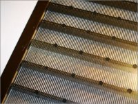
Capaciti's diaphragm which you linked to in #93 (attached below) shows at least four silicone dots across the stator (more are not visible). This makes me wonder whether the membrane might not "prefer" to vibrate in sectons with the dimensions diaphragm width x stator support distance rather than panel length x distance between silicone dots. In other words, one might achieve many narrow vibrating areas with the width of the panel as the longest vibrating length rather than a few strips as long as the panel. Do we know what actually happens?
This being so, I would expect your earler ESL that you linked to (post #191 in http://www.diyaudio.com/forums/planars-exotics/109789-esl-diaphragm-coating-20.html#post1942380), which had dots at 1/3 and 2/3 of the wire stator width, would produce three long vibrating sections in the diaphragm. I guess this was your intention. In a later ESL build (post #23 in http://www.diyaudio.com/forums/planars-exotics/245454-glue-wire-stators-3.html) you had what I take to be fixed strips to which the diaphragm was glued, dividng the diaphragm into three long strips 3.25" wide.
Capaciti's diaphragm which you linked to in #93 (attached below) shows at least four silicone dots across the stator (more are not visible). This makes me wonder whether the membrane might not "prefer" to vibrate in sectons with the dimensions diaphragm width x stator support distance rather than panel length x distance between silicone dots. In other words, one might achieve many narrow vibrating areas with the width of the panel as the longest vibrating length rather than a few strips as long as the panel. Do we know what actually happens?
The reason I started experimenting with silicone dots, is just as explained in the Audiostatic patent. If you have a wide panel and have the diaphragm tensioned for low resonance as needed for full range ESL, you can’t apply very high bias voltage before the diaphragm collapses to a stator. A few silicon dots down the centerline provides stability without raising the resonance frequency too much or eating up valuable radiating area. I switched to using strips instead of silicon dots in my later panels because low resonance was no longer a goal. Using higher resonance and crossing over to a subwoofer in the 70Hz-80Hz range provides 90% of the benefits of a full range ESL but with +5dB to +10dB more output capabilility. Capaciti, on the other hand, described his prolific use of silicon dots as a method of controlling the resonance modes of the diaphragm. I experimented a little with this concept without much success, trying 1, 2, & 3 even and staggered arrangements. I switched to damping the resonance modes with acoustic resistance from fine mesh like Quad does in their ESL63 and descendents.Bolsert, Thanks for #91 which clarifies that the silicon dots trap the diaphragm at that point, preventing vibration.
I believe you are asking if the diaphragm will have vibration modes with nodes and anti-nodes spaced across the width in addition to modes where they are spaced along the height. They answer is yes, both occur. But since the width is so much narrower, the frequencies involved will be much higher. As golfnut mentioned back in Post#64, at higher frequencies, the resistive component of the radiation impedance is orders of magnitude larger than it is at lower frequencies and provides even more damping than the mesh would.This makes me wonder whether the membrane might not "prefer" to vibrate in sections with the dimensions diaphragm width x stator support distance rather than panel length x distance between silicone dots. In other words, one might achieve many narrow vibrating areas with the width of the panel as the longest vibrating length rather than a few strips as long as the panel. Do we know what actually happens?
You may have already seen these, but just in case here are some posts with some description and images of diaphragm vibration modes.
http://www.diyaudio.com/forums/planars-exotics/168069-esls-have-bad-decay-plots-2.html#post2209785
http://www.diyaudio.com/forums/planars-exotics/168069-esls-have-bad-decay-plots-2.html#post2209798
Wow, I had forgotten all about posting these measurements where you can see the resonance nodes and anti-nodes along the height of a panel.
http://www.diyaudio.com/forums/planars-exotics/168069-esls-have-bad-decay-plots-2.html#post2209896
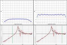
Seeing this reminded me I had performed another interesting set of measurements on diaphragm modes that I had meant to post. The subject panel was 64” x 3 1/4”, and measurements were taken every 2” along the height of the panel. I could then plot response as a function of position to show the shape of the diaphragm modes. Just for fun, I made a short video clip showing the changing in diaphragm mode shapes as frequency is swept from 30Hz to 200Hz. I find it fascinating to watch as the mode shape transitions to higher orders and different combinations. See attached *.zip file.… I had forgotten all about posting these measurements where you can see the resonance nodes and anti-nodes along the height of a panel.
After playing the video clip, you will notice that:
Attachment #1: Well below and well above fundamental diaphragm resonance, the diaphragm moves essentially as a flat piston.
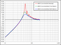
- The Blue Curve in top plot shows relative response along the panel height.
- The Red Curve in bottom plot is the response measured at the center of the panel.
- The Black Curve is the complex sum of the response measured all along the height of the panel. Basically, this is net radiated acoustic response.
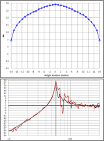
Attachment #2: At fundamental diaphragm resonance, the diaphragm moves with the expected catenary shape.
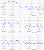
Attachment #3: Above fundamental diaphragm resonance you will find many different mode shapes and combination of modes.
Attachment #4: Comparison of net panel response with addition of damping mesh.
With damping mesh in place the complex modal behavior was damped leaving only the flat plate and catenary shapes.
Attachments
The finished ESL is about 500 mm wide by 2320mm tall – designed to fit under a 2400 mm ceiling. According to the design equations, the ESL has a nominally flat response down to 80 Hz, and then falls a way as sqrt(f) below that. In practice diaphragm resonance will boost the low frequency end – see later. I have chosen the smallest segments to be 12 mm wide to ensure minimal diffraction effects from the finite segment width.
The stators are manufactured from eight sections of 1100 mm x 384 mm x 0.8 mm PCB with 3 mm wide slots. They are reinforced with acrylic ribs glued in between the slots, every 40 mm. The spacers are also acrylic, 3.0 mm. The final stator-diaphragm spacing is less than 3mm due to half a dozen coats of acrylic lacquer. I have used copper tape as the stator ring on the rear stator, 3.5 um Mylar (supplied by Rob McKinlay), and spray-on Licron (NZ supplier available). I used the technique recommended by Rob to attach the diaphragm – stretched on an old glass shower panel using duct tape, to constant tension, and glued using slow setting epoxy.
Hi golfnut,
I tried zooming in on the picture in your second post to try and see more detail, but it's too blurry by the time I do so.
Sure wish I could see it up-close, both for clarity and possible construction hints.
I've no idea how to even approach PCB construction of ESL, but would love to learn as much as possible.
Couple questions about these panels that I didn't see explained in the text:
You say the slots are 3mm in width, are they the same distance apart?
ie; is the remaining PCB material also 3mm wide per 'strip'?
How did you arrive at the 0.8mm thickness of the PCB? Dictated by product availability? Or is this an optimal PCB thickness? ..or?
Finally, if the copper is/was on the outside, what thickness would be optimal for PCB thickness? Is there a rule of thumb?
Again, just trying to learn as much as I can for a possible future project.
Thanks
-Steve
I tried zooming in on the picture in your second post to try and see more detail, but it's too blurry by the time I do so.
Sure wish I could see it up-close, both for clarity and possible construction hints.
I've no idea how to even approach PCB construction of ESL, but would love to learn as much as possible.
Couple questions about these panels that I didn't see explained in the text:
You say the slots are 3mm in width, are they the same distance apart?
ie; is the remaining PCB material also 3mm wide per 'strip'?
How did you arrive at the 0.8mm thickness of the PCB? Dictated by product availability? Or is this an optimal PCB thickness? ..or?
Finally, if the copper is/was on the outside, what thickness would be optimal for PCB thickness? Is there a rule of thumb?
Again, just trying to learn as much as I can for a possible future project.
Hi
simple really
Where you would have half a dozen wires in parallel - there would be a strip of copper on the PCB. With PCBs, its very easy to put the resistors in between the copper strips.
Yes, slots are 3 mm wide, and the PCB material between the slots also 3 mm, in my ESLs.
0.8 mm was purely a guess - I did not know any better at the time, but it is a reasonable choice. It turns out that there are reflections between the stators (imagine very fast echo of your audio). From this perspective, the thinner the stators the better - the reflections die off quicker. Additionally, the stators will flex when a high voltage is on them and they are attracted to each other - leading to distortion - this effect is reduced by making the stators as heavy as possible.
By putting the copper on the outside of the PCB, you substantially reduce the likelihood of breakdown and arcing. Also it is easy to solder SM resistors on the outside without causing breakdown too. But it reduces the strength of the electric field between the stators - if you understand Walker's equation - you have to replace the d (stator-membrane spacing) in the equations by d+t/3.4 where t is the thickness of the PCB and the 3.4 is the dielectric constant of FR4 PCB material. The capacitance of the stators is reduced by a similar factor. The net effect is a reduction of perhaps 20% in the ESL sensitivity, which is noticeable but not a big deal you should be able to increase the polarising voltage by a bigger factor anyway. One downside of copper on the outside is greater risk of electrocution with dumkopfingerpoken.
regards
Rod
I forgot to add - the total number of slots that had to be machined in my ESL was 10,000. The QUAD ESLs have perhaps the best arrangement - 2 mm circular holes in hex pattern. In my stators that would require about 500, 000 holes !! - ESLs are thousands of holes singing in unison.
So you really need CNC machine or commercially made PCBs, which is not outrageous these days if you use a modular design - e.g. 4 x 450 mm x 450 mm PCBs for each stator - 16 PCBs for a pair of ESLs. Not cheap, but as I've mentioned before - there is a conservation of agony principle - ease of manufacture (and effort) versus cost.
R
- Status
- This old topic is closed. If you want to reopen this topic, contact a moderator using the "Report Post" button.
- Home
- Loudspeakers
- Planars & Exotics
- Another segmented ESL