
Amplifier simulation works perfect for 2hz to 200000 HZ. ") with wide input signal.
with wide input signal.
You won't be able to see any distortion with perfect sinewave as input.
Amplifier works within its parameters. Have to do with actual components and see how it perform.
Is there any other simulation software , we can test distortion?.
Its a mini amplifier. I don't need to use it to 100% of its amplificaion. I still don't like power output stage as 50% of ac signal get dropped and dissipated on 8.2 ohm emitter resistor.
All the power output stage circuit i have seen in the web and this website is nothing but AB amplifier and gets called as CLASS A amplifier. All people are cheating!.
There is no "perfect" pure CLASS A output stage. I have n't seen one yet.
Thanks again for all the reply. (BOLD red letters don't help).
Thanks
Alexk
with wide input signal. You won't be able to see any distortion with perfect sinewave as input.
Amplifier works within its parameters. Have to do with actual components and see how it perform.
Is there any other simulation software , we can test distortion?.
Its a mini amplifier. I don't need to use it to 100% of its amplificaion. I still don't like power output stage as 50% of ac signal get dropped and dissipated on 8.2 ohm emitter resistor.
All the power output stage circuit i have seen in the web and this website is nothing but AB amplifier and gets called as CLASS A amplifier. All people are cheating!.
There is no "perfect" pure CLASS A output stage. I have n't seen one yet.
Thanks again for all the reply. (BOLD red letters don't help).
Thanks
Alexk
If you use 1 resistor 8 Ohm in half output stage
and let 1 Ampere flow ( 8 Volt across 8 Ohm = 1 A )
and a loudspeaker 8 Ohm,
this output in fact has to drive 8 Ohm resistor + 8 Ohm loudspeaker.
This makes = 8 parallell with 8 = 4 Ohm.
Power-Rms = (Upeak x Upeak) / (2 x R)
1 A x 4 Ohm(resistor+LSP) = 4 Volt peak
Power over LSP:
P = ( 4 x 4 ) / ( 2 x 8 )
P loudspeaker = 1 Watt
Power over 8 Ohm resistor is the same.
P resistor = 1 Watt
========================
If replacing 8 Ohm resistor with a Constant current source,
a transistor, with 1 A current flow
you get more power out
because a CCS has nearly infinite resistance.
The total load is 8 Ohm LSP parallell with infinite resistor.
Which gives load is 8 Ohm
1 Ampere x 8 Ohm = 8 volt peak output.
Power in LSP:
P = ( 8 x 8 ) / (2 x 8 Ohm )
P = 4 Watt
========================
Summary:
Using a power resistor in output stage to set current
gives an additional load, that is parallell to other load at output terminals.
This lowers the effiency and increases the lost power.
Using a CCS, Constant Current Source
in single ended configuration increases effiency.
Gives more output per the idle current flowing.
Using push-pull transistors in output
is even more efficient than one active transistor + one CCS transistor.
For same idle current, you get four times ( 4x ) more power output
using a push-pull.
============================
There are 3 main ways to organize the output for a Class A amp.
For 1 Ampere current in output stage
you get the following output power with 8 Ohm LSP:
Resistor 8 Ohm : 1 Watt RMS
CSS transistor: 4 Watt
Push-Pull stage: 16 Watt
Max theoretical effiency, Output power vs. Idle power:
Resistor : 8.33 %
CSS Trans: 25.0 %
Push-Pull : 50%
This shows why Push-Pull output with complementary transistors (NPN+PHP)
are so popular.
All the above regarding full, pure Class A amplifiers.
=============================
It should be noted, that even if low effiency,
Resistor and CCS
has been used/prefered in many Nelson Pass designs.
The power output in some of his legendary amplifiers
has only been like 5-10% of the idle power dissipation.
Great explanation lineup. Thanks.
The only way to find out sound quality of those 3 styles is do it and find it yourself. i think.
I think i prefer CCS method. I raised the CCS output stage method few posts earlier and i did n't get good responses in my previous posts in another thread.
Is there a one CCS based on one transistor? . I know a CCS circuit uses 3 transistors.
Time for some simulation with all 3 output style. M goal is make a circuit with few active components but extremely good quality sound.
I don't like capacitors in my amplifiers design. But i have to use 3 capacitors total.
1. input capacitor to prevent high DC input signal get into my Driver stage and damage.
2. A capacitor in Driver stage output to increase AC signal gain sensitivity.
3. Output capacitor to prevent Speaker damage by DC voltage.
There is one more thing i noticed , i don't see any fan in any of the high end amplifiers. Is it because it induces EMF noise into amplifiers?.
Thanks again.
Alexk.
Greetings from Norfolk (in the snow !)
Your earlier reply
"Amplifier simulation works perfect for 2hz to 200000 HZ. with wide input signal.
You won't be able to see any distortion with perfect sinewave as input. "
Do you understand how most simulations operate - for active circuits they analyse the dc conditions to determine the operrating points for the active components, then generate an ac circuit where, for example, the collector circuit of a transistor is replaced by a current controlled current source in parallel with a resistor (I controlled by base current, resistor the collector resistance of the device).
This is then used together with the relevant passive components to simulate the operation.
All simulations I have used have performed in this way, and as such take no account of the non linearity of the collector characteristics of the device, nor in some of the programmes the limits imposed by the supply rails.
Distortion undr these circumstances can only be assessed by repeated simulation of the dc operation of the circuit, with varying dc conditions applied to the input (care being taken to 'bypass' the coupling capacitors) This often requires that each active device be modelled individually and the results plotted to determine the linearity of the circuit.
From the above it is obvious that in most cases any signal 'applied' to a circuit will not show any distortion in a simulation.
"M goal is make a circuit with few active components but extremely good quality sound.
I don't like capacitors in my amplifiers design. But i have to use 3 capacitors total. "
1. input capacitor to prevent high DC input signal get into my Driver stage and damage.
2. A capacitor in Driver stage output to increase AC signal gain sensitivity.
3. Output capacitor to prevent Speaker damage by DC voltage."
Without a fuller understanding of electronics I think that you are unlikely to acieve your objective - of the three capacitors you note above, the third (output C) can be removed by use of split rails, push-pull output and the correct feedback.
The second C you note (increased ac gain) will also provide some low frequency cut off - nomally considered to be needed to prevent sub audio signals from damaging speakers.
I have been using an amplifier for a number of years which is dc coupled to the speakers - careful design of the power supplies and the switch on voltage 'ramping' prevented serious audible popping on the speakers. The distortion to this amplifier was measured when built at various output power levels, and the one fact I remember was that the distortion meter (Radford) ended up indicating a distortion equal to that of the driving oscillator !!
AND, the amplifier sounds brilliant when driving speakers.
I have also been using an headphone amplifier which is also dc coulpled to the cans. This is based, loosely, upon power amplifier design, is obviously push pull, and performs very well. Distortion is minimal (the exact value I have forgotten), as measured using an fft input to a scope.
You also omit the use of a capacitor to reduce the amplifier gain at high frequencies where instability could occur - it is normal to define a roll off frequency for an amplifier where the gain will reduce to precvent this instability. The higher the power of the amplifier the more important this becomes.
I would strongly urge you to obtain a good book on electronics and amplifiers and carefully study it before you procede further, also to obtain an understanding of how the simulation you are using operates, together with its limitations.
You appear to accept the answers it gives as gospel, they are not - they need interpreting with knowledge of the principles of operation, and then (usually) the input circuit amending in the light of the findings.
Richard
hi ganthalf(richard),
Thansk for you valuable input. I may not know lots of stuff. I am in this forum to get different perspective based on each individual experience.
Every component induce some distortion. Each component has some purpose. I will evaluate need for each component based on what is my goals are.
Your experience with push-pull stage makes me think , it might work.
What simulation software you use to design your circuit?. Linearity range of amplifier is small. My idea is to create multiple sensitivity input to deal with different input signal.
I will writre down purpose of each and every component and eliminate any unnecessary componenet in signal path.
I will post my simulation with push pull out put stage tomorrow.
I am basically in simulation stage until i find a circuit which satisfies all my goals.
Less component better sound.
Thanks again for your input. (as far as me getting Horowitz, i know enough about electronics. Not expert though. I may not communicate properly somethings. Thats ok. no one is perfect)
Post your dream circuit , then i know what you know of.
Thanks
ALexk
boxedin said:Is there a one CCS based on one transistor? . I know a CCS circuit uses 3 transistors.
I see you really like to do things the hard way. Consider that you may have to 'un-learn' many things you have 'learned' if you prociede in this manner. OTOH, different strokes for different folks and all...
It is quite amazing to me that you know a CCS with 3 transistors, but have never seen the most BASIC (there's that word again) which uses only one (and yes, there is one, it requires a minimum of 3 components including transistor). Since you like to find things out for yourself, I am not going to draw it here for you, but I can tell you that knowing the basics of BJT operation the soultion is quite obvius.
As far as your simulation and 'not seeing' any distortion in the output sine wave, it takes a good couple of % of distortion (sometimes more) to see a visually distorted sine wave. As with any tool, you have to learn how and what the simulator actually does, maybe not in detail but at least in PRINCIPLE (there's THAT word again!).
ilimzn said:
It is quite amazing to me that you know a CCS with 3 transistors, but have never seen the most BASIC (there's that word again) which uses only one (and yes, there is one, it requires a minimum of 3 components including transistor). Since you like to find things out for yourself, I am not going to draw it here for you, but I can tell you that knowing the basics of BJT operation the soultion is quite obvius.
There are other examples of people comming up with even quite complex schematics of amplifiers like our dear friend Ben...
ilimzn said:
As far as your simulation and 'not seeing' any distortion in the output sine wave, it takes a good couple of % of distortion (sometimes more) to see a visually distorted sine wave. As with any tool, you have to learn how and what the simulator actually does, maybe not in detail but at least in PRINCIPLE (there's THAT word again!).
Visually it's much harder to see a distorted sine wave trace.
That's (one reason) why DSO's for instance have for long time used only 8 bit DAC's while Philips came up with 16 bit CD in the early 80's when DSO's where quite rare...
Cheers Michael
Happy and sucessful year to all.
I have used various simulation software packages over the years.
The first was the IBM software on an IBM mainframe, card input (a thing of the past) and batch processing.
Next I used a programme writen by a colleague which incorporated non linear elements into the analysis in a better way, but but only performed dc analysis.
Next I used a commercial package called MCAP I think, this ran on a PC and handled ac, dc and transient analysis, but the ac was limited to lenear models of devices (diodes, transistors etc.)
Probably, finally, I have used MicroSim, a very useful PC based simulation software
I would say though, that in design they are only used to investigate detail of the circuit once the design has been nearly established by calculation - one works out the circuit values etc. using Ohms law and basic device characteristics - there is a saying that if you cannot work out the basic design using ohms law (and its extensions - Thevenin, etc.) then it is too complex or you don't understand it properly.
Simulation is normally used only to trim values, investigate transient behaviour and confirm design parameters prior to building a bread board.
Concerning the circuits of the amplifiers I use, I do not have a circuit which is in a publishable form, but will try over the next few days to generate one. Watch this space !
Happy New Year
Richard
boxedin said:What simulation software you use?.
I have used various simulation software packages over the years.
The first was the IBM software on an IBM mainframe, card input (a thing of the past) and batch processing.
Next I used a programme writen by a colleague which incorporated non linear elements into the analysis in a better way, but but only performed dc analysis.
Next I used a commercial package called MCAP I think, this ran on a PC and handled ac, dc and transient analysis, but the ac was limited to lenear models of devices (diodes, transistors etc.)
Probably, finally, I have used MicroSim, a very useful PC based simulation software
I would say though, that in design they are only used to investigate detail of the circuit once the design has been nearly established by calculation - one works out the circuit values etc. using Ohms law and basic device characteristics - there is a saying that if you cannot work out the basic design using ohms law (and its extensions - Thevenin, etc.) then it is too complex or you don't understand it properly.
Simulation is normally used only to trim values, investigate transient behaviour and confirm design parameters prior to building a bread board.
Concerning the circuits of the amplifiers I use, I do not have a circuit which is in a publishable form, but will try over the next few days to generate one. Watch this space !
Happy New Year
Richard
Greetings from Norfolk
Have had a couple of hours to work on this, so have generated circuit for headphone amplifier - geneeral circuit - values will be added later - have not had time to rework them to mey satisfaction.
I admit that the front end of the amplifier is an IC, but it is based upon a design which was realised in discreet devices.
The original cct had a total harmonic distortion as low as 0.0001%, over the full audio range !!
I will try to scan this later and send it in to the group.
Happy New Year
Richard
Attachments
Both RA resistors can be replaced by constant current sources.
I have built a similiar amp.
Using NE5534 for Op-Amp and a Class A output stage.
But I used another way to setup output stage.
I also used one separate power supply for Op-Amp + resistors that bias the drivers.
And another for current to output stage itself.
I will see if I will make a drawing of my circuit.
I built it like 10 years ago, but I have recently examined it
and put the components onto a paper.
It does not give too much power, as I had only
a trafo 2x12 V 30 VA to use for power.
But it is good enough and gives like 4-5 Pure Class A Watts.
To be true it is not quite right call it class A,
as NE5534 probably works in AB when driving it.
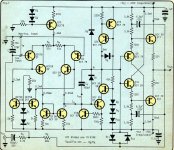
Greetings from Norfolk
I agree with you that a CCS could replace both RAs as drawn, but the (original) and fuller version of this cct. has the output bootstrapped to the middle of th RAs, thereby giving an increased linearity with higher levels of output drive.
As I said I would scan the original cct. I have now done this, and attach it - no IC s, and a spec for distortion to dream of
V. Gain 30 dB
Small Sig. BW 1MHz
Unity Gain Frequ. 26 MHz
Total Harmonic Distortion
20 to 20000 Hz, 20 V p-p Rload 1.2 K Ohms <= 0.0001 %
Slew Rate +/- 9V / us
Supply Current +/- 25 mA
Based upon prototype.
Richard
boxedin said:Every component induce some distortion. Each component has some purpose.
As we seem to be on a learning curve here, just a short contribution from my side. Be careful of the above argument, Boxedin. The two statements can be contradictory.
The superficially logic idea that no component is perfect (to word it somewhat differently) sounds pious but cannot be normative. E.g. in an amplifier with some distortion, one can apply negative feedback to reduce that distortion to an inaudible level. That would however mean that you introduce extra components. In a manner of speaking it would mean that the extras then do not do the job of distortion reduction perfectly, but the device is still better with those extras than without them.
Your second statement is overruling. Each component should serve some purpose.
Regards.
- Status
- This old topic is closed. If you want to reopen this topic, contact a moderator using the "Report Post" button.
- Home
- Amplifiers
- Solid State
- Another question about class A.