.
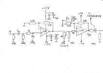
I'm not a big fan of variable gain (too many variables), so I thought I'd offer an alternative.
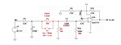
Here Ra simply cuts the input level by an arbitrary 50% as shown. It could be any value.
(Or for that matter make Ra a pot and omit--or not--S1.)
Input impedance is Rb || R26.
The values for Ra, Rb, and R26 are pretty much arbitrary. Having them all equal makes calculations--if any--easier.
.
I'm not a big fan of variable gain (too many variables), so I thought I'd offer an alternative.
Here Ra simply cuts the input level by an arbitrary 50% as shown. It could be any value.
(Or for that matter make Ra a pot and omit--or not--S1.)
Input impedance is Rb || R26.
The values for Ra, Rb, and R26 are pretty much arbitrary. Having them all equal makes calculations--if any--easier.
.
Attachments
Last edited:
Agree with much of the above. Most preamps with an output stage have too much gain. 1X or 2X is often completely adequate.
Whenever possible, invert!
The MOSFET amp is stinky compared to almost anything else you could do. If I were terribly attached to it, I'd add an opamp, a big heat sink and a current sink, and make it a proper class A with feedback.
Self shows a neat technique for reducing noise. You can get lower noise by using a low value pot, driven by a decent opamp, than the usual high value volume pot. Maybe lower than you really need, but if you're building something why not go for the max. He also has some valuable info on RIAA preamps- strongly recommend Self's small signal design book.
Measure your Sources.
Measure what your current listening voltages are.
Make an assessment of what gain if any might be needed for some of your lowervoltage sources.
Don't guess, be informed and make decisions.
ok, I did some calculations.
My current sources are 1.23v, and 2v rms as per the manuals. Use 1.23v as standard. This will also give a decent amplification if we do get lower voltage like 0.75v rms sources.
Headphones, - 32 ohms, 98db/mw, 100mw max input power. Plan to purchase some 600 ohms headphones also.
With my 32 ohms phones, if I want 115db, I need 17db more. Gives me
64mW. So lets shoot for 100mw as my headphones are also rated for 100mw.
I = sqrt(0.1/32) = 56ma V=0.056*32 = 1.792v, lets say 2v
So I need a gain of about 1.7x to go from 1.2 to 2v
Assuming same power of 100mw for 600R headphones, I get I = sqrt(0.1/600) = 13ma V = 0.013*600 = 7.8v
A gain of 6.3 will take 1.23v source close to that level.
1K and 1.5K give me 1.66x gain.
2nd stage gain = 6.3/1.66=3.8x
1K and 560 ohm give me 3.68x.
total gain = 6.1x
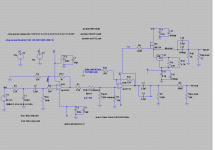
Changed schematic is attached.
Attachments
Last edited:
I might add the resistor for the cd player input before input selector..
I'm not a big fan of variable gain (too many variables), so I thought I'd offer an alternative.
Here Ra simply cuts the input level by an arbitrary 50% as shown. It could Input impedance is Rb || R26.
The values for Ra, Rb, and R26 are pretty much arbitrary. Having them all equal makes calculations--if any--easier.
.
Whenever possible, invert!
The MOSFET amp is stinky compared to almost anything else you could do. If I were terribly attached to it, I'd add an opamp, a big heat sink and a current sink, and make it a proper class A with feedback.
Self shows a neat technique for reducing noise. You can get lower noise by using a low value pot, driven by a decent opamp, than the usual high value volume pot. Maybe lower than you really need, but if you're building something why not go for the max. He also has some valuable info on RIAA preamps- strongly recommend Self's small signal design book.
You mean use inverting gain stage?
Looks like everyone hates the mosfet. Will change it and add an opamp with feedback to control it. If mosfet is the worst option, what are some of the better options. If it has good performance and can do atleast 50-60mw in class A, I am open to it.
I saw that, but there are pots that are just 50mw. might be an issue with their low power ratings. I will try lower than 10k pots and see how well those work when I build the circuit. Or are you refering to some opamp based volume control.
You could use a nice lateral FET there ")
I'm not keen on your biasing arrangement of the FET via the 100k ground referencing resistor after the coupling caps from the opamp. Its not foolproof because you could connect the preamp output to something that has a voltage present... unlikely but its not good design. Better to take the FET feed from the opamp output instead (which will be at zero volts). I'd go with Conrads suggestion of adding a current sink too.
I'm not keen on your biasing arrangement of the FET via the 100k ground referencing resistor after the coupling caps from the opamp. Its not foolproof because you could connect the preamp output to something that has a voltage present... unlikely but its not good design. Better to take the FET feed from the opamp output instead (which will be at zero volts). I'd go with Conrads suggestion of adding a current sink too.
Inverting stages are just better behaved. I think it was Jim Williams who said, when in doubt, invert. Not sure, but I think distortion is usually better in that configuration. Obviously you can't do that if you need high input impedance. In my RIAA preamp I use a non-inverting gain stage for the MM input, with very low resistor values, but the actual RIAA section is run inverting. FWIW, I like the LME49710 for those two because it has no trouble driving low resistance values, especially in the first stage where the signal levels are always small.
It's almost universal practice to use 25k to 250k for volume controls. That means you're stuck with the Johnson noise of that resistance. Result is that almost all decent preamps have similar best noise specs. It turns out that one can do quite a bit better by using a lower resistance control (or stepped attenuator) and driving it with a suitable opamp, or even a pair running in parallel (which can cut the noise even further). Remember too that signal to noise ratio is set at the first active stage, and after that the circuitry can only make it worse, never better.
If you really get crazy, Self shows how to synthesize a 47 kohm input resistor to get lower noise than a physical 47 kohm resistor, but I haven't tried that.
Last edited:
Inverting stages are just better behaved. I think it was Jim Williams who said, when in doubt, invert. Not sure, but I think distortion
is usually better in that configuration. It's almost universal practice to use 25k to 250k for volume controls. That means you're stuck
with the Johnson noise of that resistance. Result is that almost all decent preamps have similar best noise specs.
The common mode signal is zero in the inverting topology, since the positive input is grounded. It's better to not have any, than to try to reject it.
I've always used 10k volume controls in non-tube circuits. The 2.5k output resistance is even low enough to drive a short low capacitance cable directly.
Measure ...................
Measure ..........
Make an assessment of what ...... might be needed for ...........
Don't guess, be informed and make decisions.
+1

Sadly often forgotten around here
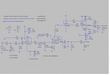
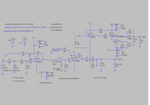
I added an opamp to control the mosfet. Also reduced the Iq to 158ma. Now the distortion numbers look much better. Schematic is attached.
Some numbers:
With 32 ohm load, 1.66x gain, 1vrms signal, max volume, I get 1.83v, 57ma, 105mw, THD - 0.0017%
FFT with 1khz signal. 2khz - 120db, 3khz 140db, 4khz 154db
With 600 ohm load, 6.1x gain, 1vrms signal, max volume. I get 6.7v, 11.2ma, 76mw, THD - 0.000126%
FFT with 1khz signal. 2khz - 124db, 3khz 139db, 4khz 154db.
same setup with 2v input clips at about 75% volume.
Both mosfet and lm317 dissipate about 2.5-3.5w each.
Could someone suggest a simple and better current sink than the lm317 that I am using currently or is it good enough. What about the output stage, can I do better than this.
Attachments
It looks very workable and a lot of this comes down to personal choice rather than right/wrong. I've never used a voltage reg in current mode (for audio) but I know many do. The alternative is a classic ring of two transistor sink.
Only other comments I would make, and again no right and wrong, is whether you want the FET wrapped in the feedback loop of the opamp. Try with and without for sonics. If your designing a PCB then its no problem to have an alternate link/jumper to select one or the other. Do you even need that opamp ? Why not just drive the FET from the OPA directly. R11 and R13 have that "its better to include them" look, but in practice they serve no real purpose.
Only other comments I would make, and again no right and wrong, is whether you want the FET wrapped in the feedback loop of the opamp. Try with and without for sonics. If your designing a PCB then its no problem to have an alternate link/jumper to select one or the other. Do you even need that opamp ? Why not just drive the FET from the OPA directly. R11 and R13 have that "its better to include them" look, but in practice they serve no real purpose.
If I change my second stage to inverting, in the low gain mode it will be working in unity gain. Is inverting a better option at unity gain also.Inverting stages are just better behaved. I think it was Jim Williams who said, when in doubt, invert. Not sure, but I think distortion is usually better in that configuration. Obviously you can't do that if you need high input impedance. In my RIAA preamp I use a non-inverting gain stage for the MM input, with very low resistor values, but the actual RIAA section is run inverting. FWIW, I like the LME49710 for those two because it has no trouble driving low resistance values, especially in the first stage where the signal levels are always small.
I will take a loot at it. I am also not all that enthusiastic about 317 in signal path.It looks very workable and a lot of this comes down to personal choice rather than right/wrong. I've never used a voltage reg in current mode (for audio) but I know many do. The alternative is a classic ring of two transistor sink.
Only other comments I would make, and again no right and wrong, is whether you want the FET wrapped in the feedback loop of the opamp. Try with and without for sonics. If your designing a PCB then its no problem to have an alternate link/jumper to select one or the other. Do you even need that opamp ? Why not just drive the FET from the OPA directly. R11 and R13 have that "its better to include them" look, but in practice they serve no real purpose.
The distortion levels are down big time with the opamp. I see both the approaches being taken by people with their designs. sonically how would these two differ.
I do plan to make a pcb and test with a home made one. I can try to put jumpers and try both of them as you describe.
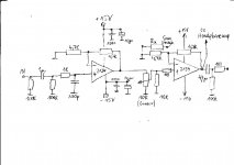
Inverting is fine for gain of 1. If you want to switch the input resistor to the inverting stage, that's a pretty benign way of doing it. IMO, if feedback is wrapped around the MOSFET opamp, the performance of the current source isn't that important. The 317 should be fine and so would any other common way of doing it. If you go open loop, then I'd look at it more closely. I did a headphone amp using a similar circuit, with an opamp and feedback, and a very simple current sink consisting of another MOSFET with a fixed gate voltage, and it sounded great. I did a more complicated version with a much better current sink and it sounded the same. Someone else here built the circuit and had trouble with oscillation, but a tiny bit of local capacitance around the opamp took care of it. The circuit is here, post #19. Primitive, but works well- you don't need to bias it near that high.
Last edited:
at gains of less than 2 it makes a small difference between inverting and non inverting.If I change my second stage to inverting, in the low gain mode it will be working in unity gain. Is inverting a better option at unity gain also.
As the gain approaches 1 the difference increases a bit.
Some opamps are designed to be almost immune to this added distortion due to common mode voltage.
As far as I know, balancing the impedances seen by the two inputs cancels the added distortion in the opamps that are not specifically designed to be immune.
Alledged distortion of inverting vs non-inverting is almost a non issue.
I tried the inverting for second stage, I dont see any improvements in THD, but the main issue is that now the gain has become dependant on the pot value, so I took it out.
I made these changes to the schematic:
changed opamp to ne5532, now I see some dc offset after the opamps. I also reduced the input impedance resistor to 47k to tame the dc offset a bit. Now I see some -45mv after the first stage and -35mv after the second. Buffers are not showing any dc. I/O dc protection caps are there, so I dont need to worry right?
Changed the pot to 1k, looks fine in sims, lets see what happens when i try.
changed the 100 ohm resistor as shown in the post above. Not sure why there are two 100ks at the input.
Attachments
With the input/output DC blocking capacitors, the opamp output offset simply reduces the available maximum peak output. Not a big concern when the Vcc >>> Vpk
The output offset is mostly due to imbalance of the -IN and +IN resistances through which the input bias currents flow.
The output offset is mostly due to imbalance of the -IN and +IN resistances through which the input bias currents flow.
- Status
- This old topic is closed. If you want to reopen this topic, contact a moderator using the "Report Post" button.
- Home
- Source & Line
- Analog Line Level
- another opamp based preamp