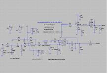
I am planning to make a preamp using opamps. I also want to include a voltage follower buffer for headphone amp and a vinyl preamp along with this in the same chassis. I plan to use a +-15v regulated supply for this from lm317/337. I am currently simulating with opa2134, but might use ne5532 as its a lot more easily available and a lot cheaper.
My current headphones are 32 and 60 ohms, but it will be good if it can cover 32-600 ohms range. Simulation seems to work fine with the preamp output, but I am struggling a bit with the headphone amp as fft shows too much distortion with the headphone output and its rising with the volume. Schematic shows IRF530, but I plan to use 510/610 in the real build. The simulation hangs if I use IRF510 and I dont have model for 610.
Questions:
1. should I test the distortion levels with a lot of frequencies, I so far have only tested with 1khz.
2. What do you use as an input voltage for signal, I am using 1v peak signal.
3. Whats a good pot value here. I am using 10k so far, how much should be the acceptable output voltage/current at low volume levels for 32/600R phones. I dont want to end up in a situation where at low volume levels also there is too much volume.
4. My mosfet source resistor calculations seem off, with a 47R R9 resistor, its giving me about 228ma of Iq. I plan to use something like these heatsinks for the mosfets. Whats a good Iq. Can it handle about 200ma. I currently see some clipping on higher volumes with 32 ohms loads on -ve rail, rest looks ok. Though I still need to find the sweet spot for pot, gain, output, Iq etc.
5. Please suggest a good ccs. How good is the lm317 ccs for this.
Please let me know if you have any good suggestions to improve this.
Attachments
Look at a switchable lower gain for the second opamp.
Might be worth looking at reducing all the feedback resistors to a lower value to reduce noise.
The opa2134 could easily drive 4k7 and should also drive 2k2 while driving the loads and parasitic capacitances.
Make sure your HF local decoupling C2, 6, 9 &12 are really close to the active devices and that they are connected to their partner with very short leads.
C12 may benefit from being a more complex arrangement.
Back to back electros to reduce the effect polarity.
The a parallel set to bring the capacitance back to 1mF. i.e. 4 caps in series parallel.
I recently did a few experiments with 4 series parallel polarised electros.
Two with -ve to -ve and two with +ve to +ve, then parallel these two series pairs.
I could not hear any difference on headphones between 4cap and no cap.
Last edited:
Try driving the SE mosfet with a sinewave and look at the "shape" of the output as you increase the level.
With a resistor load, you will find that 2nd harmonic increases quite early and creates a very non symmetrical output form.
To avoid this early onset distortion you need the maximum output to be significantly higher than the maximum peak audio signal that you want to pass through.
+10dB of overhead is probably achievable, i.e. absolute maximum unclipped output signal is 3times the highest audio signal from any source at any "loud" level.
That makes the supply requirement much higher and also makes the mosfet dissipation much higher.
You may be able to reduce the mosfet supply rail by adopting an active source instead of the resistor. Maybe a target of +5dB spare overhead would do.
You may connect the input of the headphone buffer MOSFET via R8 directly to the output pin of op-amp U1B. There's no need to A.C. couple the buffer input, since it's output is A.C. coupled, and the source should have no appreciable D.C. offset from ground. This might (or, it might not) make headphone listening a bit more transparent sounding. Whatever the result, it's easy to fiind out for yourself.
Last edited:
.
My thoughts:
If the audio source is a CD player, computer, or similar then there's no need for high Zin. Something like 20-25k would be more than enough. This is because these devices have under 1k Zout.
R1-C1 are to shunt high frequencies to ground? The OPA2134 rolls off at 100kHz by design (NE5532 does not).
U1A is a non-inverting buffer, only one resistor is needed, and that's a "just in case" resistor to prevent oscillation under some conditions.
After the output of U1A low value resistors can be used--that's the purpose of a buffer. BUT do not require U1A to drive less than a 2k load. Note that the OPA2134 will work in low impedance circuits by design. The NE5532 is happy with low impedance circuits to begin with.
The volume control shown seems to me overly complex to no very good effect (unless I'm missing something). You might do better to go to a full-on baxandall volume control (Google) between U1A and U1B, or else the classic hang-a-pot-on-the-front-end input circuit shown. The suggested input circuit has a Zin of about 25k, the parallel value of the 50k pot and R26.
Unless you specifically want to use a MOSFET driving stage you might do as well to use paralleled NJM4556s a la the O2 (oh-two, not zero-two) amp and others. The arrangement shown will drive pretty much any headphones known to man.
NOTE WELL: The NE5532 has a worst-case bias current of one microamp. Across high value resistors and amplified this can result in significant DC offset at the output. This is undesirable, but not necessarily a disaster, for speakers, but quite possibly damaging to headphones. The OPA2134 has much lower bias current so this is not a problem unless you use very high value resistors and/or high gain.
<< ...test the distortion levels... >>
If you want to do this just for fun then I wholeheartedly support the idea. But in theory, and largely in fact, resistors don't affect the audio signal. This means that a combination of op amps and resistors will always give you the advertised [inaudible] distortion levels.
Capacitors do have their effect, although this is argued about. Of course for small values everybody uses Mylar film or better--"better" also being argued about.
For electrolytics I personally use capacitors rated at 50 volts, 105-degrees centigrade. My argument is that the more robust electrolyte gives better audio performance.
More than one authority has found that back-to-back (positive-to-positive) electrolytics distort less. Of course then you have to double the capacitor values, that is, for one-220uF capacitor you back-to-back two-470uF capacitors. I personally observe that these authorities are testing at extremely low distortion levels, I wonder whether there's any real-world benefit.
<< What do you use as an input voltage for signal >>
In audio "line level" rules all, and the classic line level is one volt (RMS, not peak). Unfortunately these days there's more than one definition of line level, but you still won't go wrong figuring one volt.
If you want to be a hard liner, which I can't say is unwise, figure a CD player will have something like an 0.75 volt output.
<< Whats a good pot value >>
Inside a circuit (as between U1A and U1B) lower is better. Probably the most commonly used value is 10k simply because you can buy them anywhere. Also good is 5k. 2k would be even better, but watch out, always provide your op amps with at least a 2k load at the output.
Keep in mind that when you're building a high-pass filter (such as C5-R26), then lower resistance requires higher capacitance. With this stuff everything--everything--is a balancing act.
I hope this might be of some interest.
.
Attachments
Last edited:
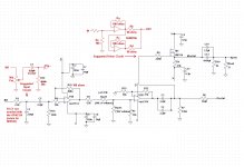
thanx guys, New circuit is attached.
Tested the voltage follower portion from the circuit below separately as you suggested. With 32 ohms, output clips at 6v or 175ma. With 600 ohms, it clips at around 9v and 15ma.
In the complete circuit, in 32 ohms with low gain, I get around 4.1v, 128ma, 520mw. With 600 ohms high gain, I get approx 9v, 15ma, max 134mw
added switchable gain. low gain is 4x and high gain is 8.4x, reduced the resistors. Are r2, r3, r5 values reasonable.Look at a switchable lower gain for the second opamp.
Might be worth looking at reducing all the feedback resistors to a lower value to reduce noise.
The opa2134 could easily drive 4k7 and should also drive 2k2 while driving the loads and parasitic capacitances.
Didnt get that, you mean use 4 caps in the regular series parallel arrangement or like bipolars?C12 may benefit from being a more complex arrangement.
Back to back electros to reduce the effect polarity.
The a parallel set to bring the capacitance back to 1mF. i.e. 4 caps in series parallel.
I recently did a few experiments with 4 series parallel polarised electros.
Two with -ve to -ve and two with +ve to +ve, then parallel these two series pairs.
I could not hear any difference on headphones between 4cap and no cap.
Try driving the SE mosfet with a sinewave and look at the "shape" of the output as you increase the level.
With a resistor load, you will find that 2nd harmonic increases quite early and creates a very non symmetrical output form.
To avoid this early onset distortion you need the maximum output to be significantly higher than the maximum peak audio signal that you want to pass through.
+10dB of overhead is probably achievable, i.e. absolute maximum unclipped output signal is 3times the highest audio signal from any source at any "loud" level.
That makes the supply requirement much higher and also makes the mosfet dissipation much higher.
You may be able to reduce the mosfet supply rail by adopting an active source instead of the resistor. Maybe a target of +5dB spare overhead would do.
Tested the voltage follower portion from the circuit below separately as you suggested. With 32 ohms, output clips at 6v or 175ma. With 600 ohms, it clips at around 9v and 15ma.
In the complete circuit, in 32 ohms with low gain, I get around 4.1v, 128ma, 520mw. With 600 ohms high gain, I get approx 9v, 15ma, max 134mw
Will test the rf filter and then take a call..
R1-C1 are to shunt high frequencies to ground? The OPA2134 rolls off at 100kHz by design (NE5532 does not).
The first stage has gain. I am not using it as a buffer.U1A is a non-inverting buffer, only one resistor is needed, and that's a "just in case" resistor to prevent oscillation under some conditions.
After the output of U1A low value resistors can be used--that's the purpose of a buffer. BUT do not require U1A to drive less than a 2k load. Note that the OPA2134 will work in low impedance circuits by design. The NE5532 is happy with low impedance circuits to begin with.
the two resistors Rpot1 and Rpot2 are just for simulation. its just a regular dual 10k pot for two channels. I am using spice variable volume to step through percentages of 10K pot.The volume control shown seems to me overly complex to no very good effect (unless I'm missing something). You might do better to go to a full-on baxandall volume control (Google) between U1A and U1B, or else the classic hang-a-pot-on-the-front-end input circuit shown. The suggested input circuit has a Zin of about 25k, the parallel value of the 50k pot and R26.
I already have O2, I want a non opamp class A output stage.Unless you specifically want to use a MOSFET driving stage you might do as well to use paralleled NJM4556s a la the O2 (oh-two, not zero-two) amp and others. The arrangement shown will drive pretty much any headphones known to man.
I might tweak the resistors to minimize the dc offset etc for ne5532.NOTE WELL: The NE5532 has a worst-case bias current of one microamp. Across high value resistors and amplified this can result in significant DC offset at the output. This is undesirable, but not necessarily a disaster, for speakers, but quite possibly damaging to headphones. The OPA2134 has much lower bias current so this is not a problem unless you use very high value resistors and/or high gain.
I will try, lets see.More than one authority has found that back-to-back (positive-to-positive) electrolytics distort less. Of course then you have to double the capacitor values, that is, for one-220uF capacitor you back-to-back two-470uF capacitors. I personally observe that these authorities are testing at extremely low distortion levels, I wonder whether there's any real-world benefit.
Just checked, some of my sources give 2v rms. I have to test with this also. I suspect it will clip at higher volume levels with this input.<< What do you use as an input voltage for signal >>
In audio "line level" rules all, and the classic line level is one volt (RMS, not peak). Unfortunately these days there's more than one definition of line level, but you still won't go wrong figuring one volt.
If you want to be a hard liner, which I can't say is unwise, figure a CD player will have something like an 0.75 volt output.
Attachments
.
Hold everything! I quoted from memory, which I shouldn't have, since I don't have one.
<< R1-C1 are to shunt high frequencies to ground? The OPA2134 rolls off at 100kHz by design (NE5532 does not). >>
In your circuit, at a gain of...er...2...the OPA2134 doesn't have significant high frequency roll off, so a low-pass filter is a good idea. My oops.
.
.
The OPA2134 rolls off at 100kHz by design (NE5532 does not). .
Really ? Are you sure.
")
.
<< the two resistors Rpot1 and Rpot2 are just for simulation. its just a regular dual 10k pot for two channels. I am using spice variable volume to step through percentages of 10K pot. >>
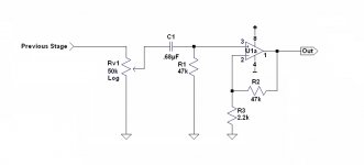
Then the non-inverting input of U1B is fed from the wiper of the volume pot? This is not common practice because now bias current for U1B comes also from the wiper, through the varying resistance of the volume control, which can make funny things happen inside the op amp.
More usual is something like as posted below. This is a snippet I had on hand, your component values will be as your circuit requires, of course. Probably Rv1 would be something like 10k log.
.
<< the two resistors Rpot1 and Rpot2 are just for simulation. its just a regular dual 10k pot for two channels. I am using spice variable volume to step through percentages of 10K pot. >>
Then the non-inverting input of U1B is fed from the wiper of the volume pot? This is not common practice because now bias current for U1B comes also from the wiper, through the varying resistance of the volume control, which can make funny things happen inside the op amp.
More usual is something like as posted below. This is a snippet I had on hand, your component values will be as your circuit requires, of course. Probably Rv1 would be something like 10k log.
.
Attachments
.
Apparently I have nothing to do but sit here looking at your schematic. Well, what the heck.
Regarding the gain resistors for U1B: R11 and R25.
Inverting amplifiers are stable with negative gain (mostly), but with non-inverting amplifiers you're taking your chances, and your chances are not good.
It can be a good idea to always have gain resistor values that are at least slightly higher than the feedback resistor (R22) value. This is because resistor values can drift, putting you into an unintentional negative gain situation.
Just to mention it in a sidebar, I still haven't figured out what R2 is for. Overcurrent protection for U1A? A more common value is 100 ohms. You just want to get some kind--any kind--of voltage drop in there.
.
Last edited:
Why use a crude MosFet stage at all?
Why not straight drive the earphones with a higher current Op Amp or maybe adding a couple push pull bipolar followers?
A single ended MosFet by definition is asymmetrical, much more so because as shown the positive side can source as much current as you want (even Amperes ) while the negative side is served by a 47 ohms resistor to ground which of course severely restricts its sink capability but worse, increases output impedance asymmetrically.
Or at least you might direct couple the MosFet and take feedback from its source terminal, so it's within the last Op Amp NFB loop.
Why not straight drive the earphones with a higher current Op Amp or maybe adding a couple push pull bipolar followers?
A single ended MosFet by definition is asymmetrical, much more so because as shown the positive side can source as much current as you want (even Amperes
) while the negative side is served by a 47 ohms resistor to ground which of course severely restricts its sink capability but worse, increases output impedance asymmetrically.Or at least you might direct couple the MosFet and take feedback from its source terminal, so it's within the last Op Amp NFB loop.
Not sure why would that cause problems and would require a cap. I thought if there is significant dc offset, only then it causes issues with the pot. Even when the pot is at the beginning of the circuit, then opamp input comes from the wiper..
Then the non-inverting input of U1B is fed from the wiper of the volume pot? This is not common practice because now bias current for U1B comes also from the wiper, through the varying resistance of the volume control, which can make funny things happen inside the op amp.
More usual is something like as posted below. This is a snippet I had on hand, your component values will be as your circuit requires, of course. Probably Rv1 would be something like 10k log.
.
.
Apparently I have nothing to do but sit here looking at your schematic. Well, what the heck.
Regarding the gain resistors for U1B: R11 and R25.
Inverting amplifiers are stable with negative gain (mostly), but with non-inverting amplifiers you're taking your chances, and your chances are not good.
It can be a good idea to always have gain resistor values that are at least slightly higher than the feedback resistor (R22) value. This is because resistor values can drift, putting you into an unintentional negative gain situation.
where's -ve gain. the gain will be 1+ 2.2k/(1k || 2.2k) = 1+ 2200/687.5 = 4.2x. With the high gain switch off it will be 1+2.2k/2.2k = 2x
will check it out and change it.Just to mention it in a sidebar, I still haven't figured out what R2 is for. Overcurrent protection for U1A? A more common value is 100 ohms. You just want to get some kind--any kind--of voltage drop in there.
.
Why use a crude MosFet stage at all?
Why not straight drive the earphones with a higher current Op Amp or maybe adding a couple push pull bipolar followers?
A single ended MosFet by definition is asymmetrical, much more so because as shown the positive side can source as much current as you want (even Amperes
Or at least you might direct couple the MosFet and take feedback from its source terminal, so it's within the last Op Amp NFB loop.
I considered the opamp option too, i already got O2 and the njm4556 is not available locally and i will have to import it. Even if I use bothchannels of ne5532 or opa2134, it will still give me only a max of some 70-80ma. Buffers come with a headache of matching transistors. I can use a 5532 and include the mosfet in the feedback loop to get some linearity. Any suggestions on what i can do with the spare channel of the opamp, or should i just use a 5534 for this.
Your gain numbers are correct.
But, I still think you have too much gain and will need a lot of attenuation for some/many of your sources.
As Bent says R2 is too high.
Try reducing to around 100r to 200r.
Since you have DC blocking at the outputs, then output offset of the individual opamps is not a big concern. But it is worth checking the DC voltages at the outputs of the opamps.
Your gain numbers are correct.
But, I still think you have too much gain and will need a lot of attenuation for some/many of your sources.
How about 3x and 6x. I could put the high gain switch to switch out R4 to make it a buffer and do 3x in the second stage.
.
<< ...the non-inverting input of U1B is fed from the wiper of the volume pot? This is not common practice because now bias current for U1B comes also from the wiper, through the varying resistance of the volume control, which can make funny things happen inside the op amp.
Not sure why would that cause problems and would require a cap. I thought if there is significant dc offset, only then it causes issues with the pot. Even when the pot is at the beginning of the circuit, then opamp input comes from the wiper. >>
I'm not talking about DC offset or op amp input.
The issue here is bias current, which has to do with the internal operation of the op amp. You can't draw bias current through a varying resistance and expect the thing to work.
Or...well, I guess maybe it would work, but something funny is going to happen. This might help: Op Amp Bias Currents
.
.
<< ...the feedback network for U1B...where's -ve gain. the gain will be 1+ 2.2k/(1k || 2.2k) = 1+ 2200/687.5 = 4.2x. With the high gain switch off it will be 1+2.2k/2.2k = 2x >>
The issue here is not the amount of gain, the issue is whether that gain is positive or negative. And this boils down to the realities of real-world components.
Assume that at some given moment only R22 and R25 are in the feedback circuit.
These resistors are equal on paper, but in the real world it doesn't work that way. Resistor values are not exact to begin with, but more importantly they can and do change with temperature, and as components age. Thus it's possible for the values of either R22 or R25, or both, to drift higher or lower.
All of which means that it's possible for these resistors to change value enough to put U1B into a negative-gain configuration, and non-inverting amplifiers are not stable with negative gain (broadly speaking).
By the way, the same applies to R4 and R15. The moral of this story is that you never, ever design on the edge. You always leave some slack not because you think you might need it, but because you know you will.
Random thought #1. If you only need a gain of two, do you really need any gain at all?
Random thought #2. It might be as well to make U1A a real buffer (unity gain), and U1B the only gain stage. Seems simpler, and with this stuff simpler = better is a given.
Random thought #3. Unless you specifically want a buffered input (an idea I always favor), I really don't see a need for two staqes in the first place.
.
Last edited:
.
<< ...the feedback network for U1B...where's -ve gain. the gain will be 1+ 2.2k/(1k || 2.2k) = 1+ 2200/687.5 = 4.2x. With the high gain switch off it will be 1+2.2k/2.2k = 2x >>
The issue here is not the amount of gain, the issue is whether that gain is positive or negative. And this boils down to the realities of real-world components.
Assume that at some given moment only R22 and R25 are in the feedback circuit.
These resistors are equal on paper, but in the real world it doesn't work that way. Resistor values are not exact to begin with, but more importantly they can and do change with temperature, and as components age. Thus it's possible for the values of either R22 or R25, or both, to drift higher or lower.
All of which means that it's possible for these resistors to change value enough to put U1B into a negative-gain configuration, and non-inverting amplifiers are not stable with negative gain (broadly speaking).
The gain for that configuration is always positive, whether its running with 100% feedback and showing a gain of unity (1) or any combination of feedback resistor. Just put the numbers in and calculate it out. You can try 2201 ohms and 2199 ohms and just swap them around. The gain is always positive. Now try 1meg and 1 ohm, and swap them around. Unrealistic values but the gain is positive in both cases.
- Status
- This old topic is closed. If you want to reopen this topic, contact a moderator using the "Report Post" button.
- Home
- Source & Line
- Analog Line Level
- another opamp based preamp