Hi C,
") Yes, I doubt I would build it this way, either. Mainly because of the difficulty to keep currents away from high impedance circuitry. Your approach with the amp on the (left) side is of course better in this respect. (How do you cool the regulator on the opposite side?)
Yes, I doubt I would build it this way, either. Mainly because of the difficulty to keep currents away from high impedance circuitry. Your approach with the amp on the (left) side is of course better in this respect. (How do you cool the regulator on the opposite side?)
The regulator portion was the same on both, right? I don't think it will cause that much of a problem unless the traces don't touch...
It's just a little more prone to ground noise and a little more difficult to 'manufacture in the kitchen'...
I've also thought about it. Even for my project. It's actually only the larger capacitors that cause difficulties, because they have to be fixed somewhere. Everything else could actually be done very compact:
- A bridge rectifier with four capacitors across it's four legs,
- two regulator ICs with four passives (each) around their legs,
- two amp ICs with eight passives (each) around their legs.
Should actually be very beautiful when both soldered and bolted symmetrically, very compact with the larger capacitors in front of the ICs, and cheap as hell!
The more I think of it, the more it feels like I should just start doing it with spare components like a KBU rectifier, LM350 regulators, LM3876 amps and some through-the-hole passives out of the box!
Sebastian.
I'm not convinced that a board with the chip on the narrow end makes any sense at all, for a lot of reasons.
Yes, I doubt I would build it this way, either. Mainly because of the difficulty to keep currents away from high impedance circuitry. Your approach with the amp on the (left) side is of course better in this respect. (How do you cool the regulator on the opposite side?)I suspect there may be some trouble on the regulator portion with respect to traces being too close together. Which may mean I just need to make it a bit wider, or find a different solution.
The regulator portion was the same on both, right? I don't think it will cause that much of a problem unless the traces don't touch...
It's just a little more prone to ground noise and a little more difficult to 'manufacture in the kitchen'...
I may just go P2P for a rats nest of beauty
I've also thought about it. Even for my project. It's actually only the larger capacitors that cause difficulties, because they have to be fixed somewhere. Everything else could actually be done very compact:
- A bridge rectifier with four capacitors across it's four legs,
- two regulator ICs with four passives (each) around their legs,
- two amp ICs with eight passives (each) around their legs.
Should actually be very beautiful when both soldered and bolted symmetrically, very compact with the larger capacitors in front of the ICs, and cheap as hell!
The more I think of it, the more it feels like I should just start doing it with spare components like a KBU rectifier, LM350 regulators, LM3876 amps and some through-the-hole passives out of the box!
Sebastian.
Hi sek-
I'm sorry for the delay, but yes I was out of town for the weekend.
The whole purpose of this project is a factory spec LM3886 board that has a thin chip mount area so multiples can be placed side by side.
If a single stereo pair is needed, a 5 channel unit is needed, or a parallel/bridge chip multi-channel unit is needed you can just add or subtract boards. Of course pwr requirements would change but pwr is it's own separate section in the chassis or separate chassis.
I can only "assume" that you are using the Unix version of Eagle since when I use the GUI (yes I am another Bill Gate captive) and click on the move button I can move the traces and some components but I can NOT move the pads. I have not figured out how to get around that just yet.
This is NOT a commercial venture, it is a hobby and the resulting boards will be available at COST to anyone who wants to build one. IF there is any money made from these boards it will be given back to the forum.
Steve @ Apex.jr does sell all of the materials to make a gainclone and he will be offering these boards in a few different kits. A beginners basic kit, add on regulation and buffer upgrades, and then multi-channel kits for HT or parallel/bridge clones.
For new people trying their first GC it will be the easiest way to construct a working amp. That is also one reason why we need hole through components and not SMD.
I promise that if I were fluent in Eagle I would not be asking for assistance and would do my own work. However being new to it and not being able to figure out the idiosyncrasies in a timely manner I have to swallow my pride and ask for assistance.
I am going to be using the same manufacturing company (Advanced Circuits) as BrianGT (WITH his granted permission). I am hoping to put 4 PCB's on a sheet with snap apart scoring like Brian's.
The only components I can comment on is the main supply caps on the PCB, I would like 440 uF or so 50v caps. The output resistors can be changed but Steve has some Dale .2 Ohm 3 Watt resistors that would work well for excellent prices.
sek: The lone reg on the "other" side of the board will just need to have its own HS.
rabstg:
Once you start adding heat-sinks to the regulators, I don't know that you're really any further ahead with the chip on the end. In my opinion, for an endeavor such as you mention where you want to allow room for an unknown number of amp boards, the orientation isn't going to make a difference. I guess I don't quite understand what case dimensions you are trying to squeeze this stuff into.
C
Hi,
I get a broader picture of the needs in that amplifier over time, but your'e still a little unspecific.
First off, something makes me wonder:
Hmm, a non-commercial venture that Apex.Jr will sell, while I shall develop it because you don't have the time to read the manual?
Sounds a little adventurous, don't you think?
Are you shure you have sorted your requirements and goals out, yet?
Why are people like Apex.Jr not able to implement a manufacturer's standard circuit themselves?
Well, I would really appreciate if you could explain what's behind the project. The DIY character of diyaudio.com actually implies that it's not a resource to get the R&D for free when doing commercial projects.
OTOH, that doesn't mean I'm unwilling to help you, even if the boards shall be sold. You just manage to surprise me everytime you answer.
The program Eagle is available for Windows, Linux and MacOS X. It does not differ between the operating systems, so every Eagle copy of the same version works the same on everyones computers.
It's really in the manual and tutorial, how it works. OTOH, I understand if you don't have the time to enter a different world for Steve, though!?
I understand your point about the SMDs, but wouldn't Brian's boards be easier for just that purpose? It seems they are so foolproof that the fraction of remaining problems or uncertainties remaining to some beginners can usually all be solved with a couple of posts on the forum.
Again, I still cannot take that size argument for the multichannel amplifier case. A unit with more than two channels in one enclosure would require a heat sinking so big that one could also use Brian's boards...
I don't know the details that Advanced Circuits work with. With 4 PCBs on a sheet, ... , what size is an Advanced Circuits sheet?
Brian?
Who can comment on the other components?
Well, I just assume standard parts. After all, there are not that many of them.
That seems the upper sensible limit for a regulated PSU and still too small for an unregulated version. How big is the 'central' capacitance in the PSU? With 440uF it should be no less than 10mF per two channels, but this could still be experimented with, later.
Do you know their size? I need the size and/or package number.
It would of course be sensible to integrate their footprint, as Steve might perhaps be able to bundle them with the kit for a longer time. Also, 3W seems okay, while 2mOhm is too large. Is that why you wanted two of them on one board? Well, we could design in two of them, but wouldn't this be more expensive for the users/buyers?
Okay. Some things got sorted out, some things still remain unclear.
What I can assume now is:
- We're using Nationals standard circuit, non-inverting with mute circuit.
- We're settling for a board width of no more than one inch, length is determined by whatever we need for everything to fit on (including mounting holes).
- Onboard supply capacitors shall have pin distance 1/5" (5mm) and diameter 2/5" (10mm).
- Onboard power resistors shall be 0817 packages or similar.
And some additional questions arose:
- What about CJD's approach?
- What about the regulator board?
- What about the cooling of multiple channels?
- What about connector placement and type (it's important to know the connector types, as they are not infinitely small )?
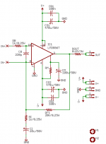
To get us going, I adopted the schematic. It now features all components you want it to have, as this now is the building block for paralleling/bridging. I've also changed the component designations to comply with National's nomenclature and included all component values.
This currently makes up for the following bill of materials:
# Value
1 0.1R/3W
2 1k/0.25W
1 20k/0.25W
1 68u/50V
2 100n
1 100u/50V
1 220p
2 470u/50V
1 LM3886T
Sebastian.
PS: Never mind, I still forgot to move the input signal ground away from the inverting input...
I get a broader picture of the needs in that amplifier over time, but your'e still a little unspecific.
First off, something makes me wonder:
This is NOT a commercial venture
Steve @ Apex.jr [...] will be offering these boards in a few different kits
Hmm, a non-commercial venture that Apex.Jr will sell, while I shall develop it because you don't have the time to read the manual?
Sounds a little adventurous, don't you think?
Are you shure you have sorted your requirements and goals out, yet?
Why are people like Apex.Jr not able to implement a manufacturer's standard circuit themselves?
Well, I would really appreciate if you could explain what's behind the project. The DIY character of diyaudio.com actually implies that it's not a resource to get the R&D for free when doing commercial projects.
OTOH, that doesn't mean I'm unwilling to help you, even if the boards shall be sold. You just manage to surprise me everytime you answer.
I can only "assume" that you are using the Unix version of Eagle
The program Eagle is available for Windows, Linux and MacOS X. It does not differ between the operating systems, so every Eagle copy of the same version works the same on everyones computers.
It's really in the manual and tutorial, how it works. OTOH, I understand if you don't have the time to enter a different world for Steve, though!?
For new people trying their first GC it will be the easiest way to construct a working amp. That is also one reason why we need hole through components and not SMD.
I understand your point about the SMDs, but wouldn't Brian's boards be easier for just that purpose? It seems they are so foolproof that the fraction of remaining problems or uncertainties remaining to some beginners can usually all be solved with a couple of posts on the forum.
Again, I still cannot take that size argument for the multichannel amplifier case. A unit with more than two channels in one enclosure would require a heat sinking so big that one could also use Brian's boards...
I am going to be using the same manufacturing company (Advanced Circuits) as BrianGT (WITH his granted permission). I am hoping to put 4 PCB's on a sheet with snap apart scoring like Brian's.
I don't know the details that Advanced Circuits work with. With 4 PCBs on a sheet, ... , what size is an Advanced Circuits sheet?
Brian?
The only components I can comment on is the main supply caps on the PCB
Who can comment on the other components?Well, I just assume standard parts. After all, there are not that many of them.
I would like 440 uF or so 50v caps.
That seems the upper sensible limit for a regulated PSU and still too small for an unregulated version. How big is the 'central' capacitance in the PSU? With 440uF it should be no less than 10mF per two channels, but this could still be experimented with, later.
The output resistors can be changed but Steve has some Dale .2 Ohm 3 Watt resistors that would work well for excellent prices.
Do you know their size? I need the size and/or package number.
It would of course be sensible to integrate their footprint, as Steve might perhaps be able to bundle them with the kit for a longer time. Also, 3W seems okay, while 2mOhm is too large. Is that why you wanted two of them on one board? Well, we could design in two of them, but wouldn't this be more expensive for the users/buyers?
Okay. Some things got sorted out, some things still remain unclear.
What I can assume now is:
- We're using Nationals standard circuit, non-inverting with mute circuit.
- We're settling for a board width of no more than one inch, length is determined by whatever we need for everything to fit on (including mounting holes).
- Onboard supply capacitors shall have pin distance 1/5" (5mm) and diameter 2/5" (10mm).
- Onboard power resistors shall be 0817 packages or similar.
And some additional questions arose:
- What about CJD's approach?
- What about the regulator board?
- What about the cooling of multiple channels?
- What about connector placement and type (it's important to know the connector types, as they are not infinitely small
)?To get us going, I adopted the schematic. It now features all components you want it to have, as this now is the building block for paralleling/bridging. I've also changed the component designations to comply with National's nomenclature and included all component values.
This currently makes up for the following bill of materials:
# Value
1 0.1R/3W
2 1k/0.25W
1 20k/0.25W
1 68u/50V
2 100n
1 100u/50V
1 220p
2 470u/50V
1 LM3886T
Sebastian.
PS: Never mind, I still forgot to move the input signal ground away from the inverting input...
Attachments
sek-
A few points to clarify then I will end this thread.
1. I scheduled the day off Friday to read the tutorial and finish the boards myself as I had hoped originally before I started working again. I left Cisco after 3.5 yrs took a month off for vacation and started this project. Then returned to work where it has been B@77's to the wall ever since which drove me to ask for out side assistance.
2. Steve is a surplus parts dealer not an Engineer. He has 90% of the parts required to build a GC at super prices. I made a deal with him that if he put together a kit for beginners I would GIVE him some PCB's to put in the kit. He declined and said he would sell the PCB's at cost so I would not be out any money. The kit will be (HANDS DOWN) the best value in a gainclone and will have upgrade capabilities to grow with the builder.
3. CJD had originally designed a PCB that was very nice but it was decided to go with a different layout profile for various reasons. Also CJD's PCB file was not available to send to the manufacturer.
4. Regulator board is next. I have it in mind but have not started the layout as of yet.
5. The kit options will include different style chassis to accommodate various cooling needs.
6. No connectors on the board. Only wire soldered similar to BrianGT's.
7. BrianGT is the one who suggested Advanced Circuits as the PCB manufacturer.
8. Purchasing two .22Ohm 3 W DALE resistors from Steve is STILL cheaper than one .11Ohm 3 W DALE from most other retail stores.
9. Steve and I have no ties or connections. I purchase parts from him because he sells allot of what I need at good prices. I am contributing to this kit as a favor to the DIY community. Steve will sell his parts at a profit (that's what business' do) but the PCB's will not contribute to that profit. In fact Steve has suggested that I ship the PCB's directly to the kit owners but as you can see I don't have the time to do so.
10. BrianGT's boards are excellent. But he only sells the boards. Pwr supplies, connectors, wire and chassis have to be "sourced" elsewhere. Peter sells beautiful chassis for $150 US but that kinda defeats the purpose of an in-expensive beginners project.
This is a DIY site and I want this kit to bring in additional new builders to this hobby.
This kit will be of excellent quality AND value. That is the only way I would associate my name to it. I LOVE electronics and hope to make it easy for new hobbyist to join and learn the miracle of electronic theory.
rabstg:
The board designs are available, just not in a format that is usable by your supplier of choice. But I suspect that amounts to the same thing. One of these days I'll have the time to sit down and figure out how Eagle works.
They're available for someone else to convert to Eagle if that's the direction you would like to go, for non-commercial use. The schematic is straight off the spec sheet.
The buffer boards and the regulated power board I have designed would require permission from others since the schematics are not mine.
Time is about as short on this end as it seems to be for you. I started this project in May.
However, I do think I agree with Steve in one respect - if you're going to offer boards to the DIY community, you should ship them direct. That was my plan, certainly.
C
The board designs are available, just not in a format that is usable by your supplier of choice.
But I suspect that amounts to the same thing. One of these days I'll have the time to sit down and figure out how Eagle works.They're available for someone else to convert to Eagle if that's the direction you would like to go, for non-commercial use. The schematic is straight off the spec sheet.
The buffer boards and the regulated power board I have designed would require permission from others since the schematics are not mine.
Time is about as short on this end as it seems to be for you. I started this project in May.
However, I do think I agree with Steve in one respect - if you're going to offer boards to the DIY community, you should ship them direct. That was my plan, certainly.
C
rabstg said:I am going to be using the same manufacturing company (Advanced Circuits) as BrianGT (WITH his granted permission). I am hoping to put 4 PCB's on a sheet with snap apart scoring like Brian's.
You certainly don't need my permission to go ahead ordering from them. Advanced Circuits does great work. I have ordered boards from 4 different companies for various projects, and the Advanced Circuits are the best quality, and actually the cheapest (when you catch the great specials they are running).
They also have a free online design check utility, which gives price quotes: www.freedfm.com
Also, shipping orders out is very easy for US order if you use paypal. You can just print the postage online through the paypal website and stick the package in a mailbox. For the international orders, you need to fill out customs forms and take the package to the post office to be scanned.
--
Brian
Hi Troy,
Umm, why?
That's great news. Can we see them?
And you call that a deal?
Hmm, I've got nothing against helping in designing a board for both you and Apex.Jr to ship with kits. Really.
Nope, it's started already.
Good, that means someone at Apex.Jr would have to figure out which heatsink is available and suitable.
That's good, would save a third of the boardspace in my design.
Okay, so there will be two. Would certainly eat up the space savings from the connectors...
Yep, I agree. Overall 'system' cost is really an issue with almost all available GC kits or boards.
Troy, guess why I already invested time and effort into this board?
If I was at home now I could send you the schematic of amplifier and regulator boards now. Along with the preliminary board layouts, currently focused on exact parts location due to size reduction.
Both amp and regulator boards measure 1" by 2.25" at the moment, this could easily be reduced to 1" by 2". Smaller wouldn't be useful, I think (mounting, connecting, ...).
If you'd like to use them, just feel free to do.
If you don't, well, don't.
No hard feelings on that, it would just have been easier if I had known the consequences of my board development approach in the first place.
I will post the project files when I get home.
Sebastian.
PS: I really didn't want to force you into scheduling a day off, sorry.
rabstg said:I will end this thread.
Umm, why?
1. I scheduled the day off Friday to read the tutorial and finish the boards myself as I had hoped originally before I started working again.
That's great news. Can we see them?
I would GIVE him some PCB's to put in the kit.
And you call that a deal?
Hmm, I've got nothing against helping in designing a board for both you and Apex.Jr to ship with kits. Really.
4. Regulator board is next. I have it in mind but have not started the layout as of yet.
Nope, it's started already.
5. The kit options will include different style chassis to accommodate various cooling needs.
Good, that means someone at Apex.Jr would have to figure out which heatsink is available and suitable.
6. No connectors on the board. Only wire soldered similar to BrianGT's.
That's good, would save a third of the boardspace in my design.
8. Purchasing two .22Ohm 3 W DALE resistors from Steve is STILL cheaper than one .11Ohm 3 W DALE from most other retail stores.
Okay, so there will be two. Would certainly eat up the space savings from the connectors...
Peter sells beautiful chassis for $150 US but that kinda defeats the purpose of an in-expensive beginners project.
Yep, I agree. Overall 'system' cost is really an issue with almost all available GC kits or boards.
This kit will be of excellent quality AND value. That is the only way I would associate my name to it.
Troy, guess why I already invested time and effort into this board?
If I was at home now I could send you the schematic of amplifier and regulator boards now. Along with the preliminary board layouts, currently focused on exact parts location due to size reduction.
Both amp and regulator boards measure 1" by 2.25" at the moment, this could easily be reduced to 1" by 2". Smaller wouldn't be useful, I think (mounting, connecting, ...).
If you'd like to use them, just feel free to do.
If you don't, well, don't.
No hard feelings on that, it would just have been easier if I had known the consequences of my board development approach in the first place.
I will post the project files when I get home.
Sebastian.
PS: I really didn't want to force you into scheduling a day off, sorry.
Hi All-
Has anyone got a minute to look over digi01's boards?
I looked over them and have not seen any obvious issues but then I don't claim to be an expert in this, just a hobbyist.
Any advice would be appreciated. I will be using multiples of these boards with regulated supplies.
Has anyone got a minute to look over digi01's boards?
I looked over them and have not seen any obvious issues but then I don't claim to be an expert in this, just a hobbyist.
Any advice would be appreciated. I will be using multiples of these boards with regulated supplies.
rabstg said:Hi All-
Has anyone got a minute to look over digi01's boards?
I looked over them and have not seen any obvious issues but then I don't claim to be an expert in this, just a hobbyist.
Any advice would be appreciated. I will be using multiples of these boards with regulated supplies.
Nothing really to be anoyed of.
In my taste the double sided PCB is not really necessary (I have built test amplifiers and measured better than -110 db rel. noise floor with a Creative Labs Audigy II USB module and SpectraLab), but if cost is no major concern, then it is OK, makes for a much better looking board.
The resistor behind the lower pin row may be a liability, if I were asked, should relocate it elsewhere.
Rodolfo
ingrast said:The resistor behind the lower pin row may be a liability, if I were asked, should relocate it elsewhere.
Rodolfo
do you mean that small cap,Cb? it is a option part,the footprint of pins is 100mil.
digi01 said:
do you mean that small cap,Cb? it is a option part,the footprint of pins is 100mil.
I was reffering to "Rn" if I read right.
Anyway if it is soldered on the PCB side opposite to the chip there is no major problem either.
Rodolfo
Hi Rodolfo-
I think the name is R"m" for the mute resistor, and it can be placed on top or bottom.
I tend to put it on bottom.
Thank you very much for your comments. They confirm my speculation that digi01 did an outstanding job.
Anyone else? See anything that could be improved?
I think the name is R"m" for the mute resistor, and it can be placed on top or bottom.
I tend to put it on bottom.
Thank you very much for your comments. They confirm my speculation that digi01 did an outstanding job.
Anyone else? See anything that could be improved?
- Status
- This old topic is closed. If you want to reopen this topic, contact a moderator using the "Report Post" button.
- Home
- Amplifiers
- Chip Amps
- Another LM3886 PCB!!