All,
Thank goodness the weather's been cold in Colorado these last few days--as a consequence, I made good headway in wiring my F5.")
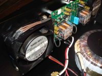
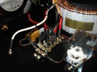
"Line side" is completed, as is the power supply. Should be testing the power supply over the next day or so, but "open" and under resistor dummy loads. Will check for all relevant "vitals" as I proceed--bus voltages, ripple, etc. Will next proceed to the vectorboard, that contains the voltage regulators for the VU meters and loudspeaker protection modules, the VU drivers, the temp monitoring circuits, and the clipping circuit LED indicators.
Some pics attached of the wiring progress. Again, comments/criticism is welcome. I remain a "reborn newbie" at this, and inputs are welcome!
The pics should be self-explanatory. Drop me a reply, if you have questions....
Ken
Thank goodness the weather's been cold in Colorado these last few days--as a consequence, I made good headway in wiring my F5.
"Line side" is completed, as is the power supply. Should be testing the power supply over the next day or so, but "open" and under resistor dummy loads. Will check for all relevant "vitals" as I proceed--bus voltages, ripple, etc. Will next proceed to the vectorboard, that contains the voltage regulators for the VU meters and loudspeaker protection modules, the VU drivers, the temp monitoring circuits, and the clipping circuit LED indicators.
Some pics attached of the wiring progress. Again, comments/criticism is welcome. I remain a "reborn newbie" at this, and inputs are welcome!
The pics should be self-explanatory. Drop me a reply, if you have questions....
Ken
Attachments
having both you and 6l6 building these F5's gets me excited for mine!
Ironically enough, i ended up with the same boards as yourself!
My amp won't be quite as complex as yours, but its still the same F5!
I only have the output transistors, the thermistors, and two other little parts on the amp to solder on, im waiting to find some alligator clips to do those!
your build is coming out excellently by the way, and am looking foreward to seeing more pictures of it!
your build is coming out excellently by the way, and am looking foreward to seeing more pictures of it!
Thanks for the kind words!
While I'm trying to keep the basic F5 design pure (i.e., it's impossible to improve upon Pass perfection!) I did want to add a few bells and whistles to the overall product. Fortunately, I can ultimately strip out my stuff if it doesn't pan out, and return to Pass simplicity.
Candidly, one thing I wanted to do with this amp was find a "home" for the two VU meters I had bought almost 35 years ago(!). They are Weston 1200 series, and use a mirrored meter movement. In the original design, they used a 5-watt automotive bulb, to shine through an orifice, onto a small mirror on the meter movement--and then projected onto the front glass of the meter face. I've replaced the incandescent bulb with a high-intensity white LED.....and the meter movement is almost mesmerizing.... I've only stumbled onto one other set of such meters--and the seller wanted $500 for the pair (I paid $25 for mine).
VU meters not the issue, I can hardly wait to hear the sound of pure "class A". I suspect my next move will be to upgrade speakers, and I plan on doing a DAC and CD transport, next.
Ken
A little more progress.....!
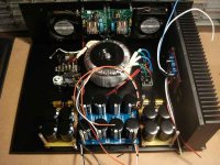
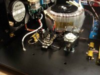
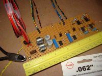
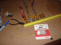
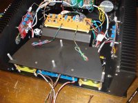
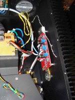
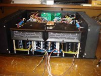
I saw a need to develop a small circuit board for some of my "ancillary" stuff. Being very rusty in PCB layout and fabrication, I opted for vectorboard. In the attached photos, the layout is (from left to right): The power input leads and LED current-limiting resistors, the 12 VDC and 5 VDC switching regulators (they run cool, even when I tested them on a 28 volt rail at 500 ma without heatsinks)...... the temperature monitors for the left and right heatsinks (in the center of the vectorboard), and the clipping monitors for the left and right channels. Sorry about the differing resistor styles, but I was max'ing use of my benchstock, where possible.
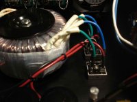
The second photo shows the "cable stack" for the board. The heavy leads are for power input, and power output (12 VDC) to the speaker protection PCBs that are mounted on the rear apron of the chassis. The three-wire leads running to the left and right of the vectorboard are for the heatsink thermistor (temp sensors) and the output sensing (for the VU meters and clipping indicators). The leads running toward the top of the pic are for the front panel leds (power, overtemp, and clipping), as well as for the VU meter drivers.
I've been asked where I got all the multi-color thin gauge wire I'm using. Years ago, I picked up a 30-foot piece of 100 conductor telephone cable (at NO cost) from an office building being stripped of an outdated central phone system. That gave me a LOT of thin hook-up wire, with unique color coding, that's been great for projects!
Lessons learned, recently: Time to get my reading glasses updated--the point-to-pont vectorbaord wiring underscored that need!....and yes, I need to get back into PCB design, layout, and fabrication..... (I now REMEMBER why I don't like to use vectorboard!)
I also tested the power supplies, and the vectorboard design--both are "looking good", and work progresses on final wiring....
I saw a need to develop a small circuit board for some of my "ancillary" stuff. Being very rusty in PCB layout and fabrication, I opted for vectorboard. In the attached photos, the layout is (from left to right): The power input leads and LED current-limiting resistors, the 12 VDC and 5 VDC switching regulators (they run cool, even when I tested them on a 28 volt rail at 500 ma without heatsinks)...... the temperature monitors for the left and right heatsinks (in the center of the vectorboard), and the clipping monitors for the left and right channels. Sorry about the differing resistor styles, but I was max'ing use of my benchstock, where possible.
The second photo shows the "cable stack" for the board. The heavy leads are for power input, and power output (12 VDC) to the speaker protection PCBs that are mounted on the rear apron of the chassis. The three-wire leads running to the left and right of the vectorboard are for the heatsink thermistor (temp sensors) and the output sensing (for the VU meters and clipping indicators). The leads running toward the top of the pic are for the front panel leds (power, overtemp, and clipping), as well as for the VU meter drivers.
I've been asked where I got all the multi-color thin gauge wire I'm using. Years ago, I picked up a 30-foot piece of 100 conductor telephone cable (at NO cost) from an office building being stripped of an outdated central phone system. That gave me a LOT of thin hook-up wire, with unique color coding, that's been great for projects!
Lessons learned, recently: Time to get my reading glasses updated--the point-to-pont vectorbaord wiring underscored that need!....and yes, I need to get back into PCB design, layout, and fabrication..... (I now REMEMBER why I don't like to use vectorboard!)
I also tested the power supplies, and the vectorboard design--both are "looking good", and work progresses on final wiring....
Attachments
Hey 6l6--how was the skiing?
I have a variac, but not "hefty enough" for this project. I did use the 100w lightbulb series shunt, though. No smoke.....so I removed the lightbulb and ran at line voltage/current..... Everything was "on the mark".
I have some final wiring to do, but have to fabricate a bracket for the vectorboard before I run any serious response/output, etc testing. Probalby in about a week.
I kinda have a schedule. I have a race car I'm been fabricating, but it's a little too cold to put in much "garage time". I'm working in the amp in the heated confines of my basement lab--but I'll migrate to the car again, when the weather warms up (later this month? early April?). I'll have the amp done, before that!
Ken
CanAm Man
good progress vero board or not.
Can you post schematics of the aux circuits?
Tanks
Al
PS No much frogress here was going to finish off my Protection board NTE7100 and Amplimo LR Realy.
But me an the VR4 are on family taxy duty..
Any way have you considered using The Amplimo relay ?
good progress vero board or not.
Can you post schematics of the aux circuits?
Tanks
Al
PS No much frogress here was going to finish off my Protection board NTE7100 and Amplimo LR Realy.
But me an the VR4 are on family taxy duty..
Any way have you considered using The Amplimo relay ?
Last edited:
Guilty, as charged....
I've had a few PMs about my Diyaudio "screen name", so at the risk of hijacking my own thread (is that even possible?) here goes:
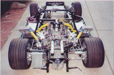
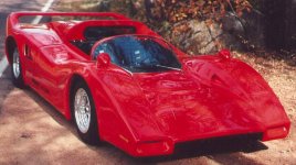
Yes. I used to race in the CanAm (Canadian-American Cup Series) in the 1970's.
Yes. I still race in these classes, as part of "historic" and vitage racing.
Yes. I scratch build these cars today, styled after the McLaren, with updated suspension and modern (turbocharged, intercooled, fuel-injected) engines of about 1,000 HP. Pics of my current four-wheeled non-audio projects attached, FYI.... (Yes, they are also street legal!)
For those interested, please PM me, and we'll keep the Diyaudio threads free from tire smoke, and gasoline pollution.
We will now return to your regularly-schedule programming.
I've had a few PMs about my Diyaudio "screen name", so at the risk of hijacking my own thread (is that even possible?) here goes:
Yes. I used to race in the CanAm (Canadian-American Cup Series) in the 1970's.
Yes. I still race in these classes, as part of "historic" and vitage racing.
Yes. I scratch build these cars today, styled after the McLaren, with updated suspension and modern (turbocharged, intercooled, fuel-injected) engines of about 1,000 HP. Pics of my current four-wheeled non-audio projects attached, FYI.... (Yes, they are also street legal!)
For those interested, please PM me, and we'll keep the Diyaudio threads free from tire smoke, and gasoline pollution.
We will now return to your regularly-schedule programming.
Attachments

The Build Continues....
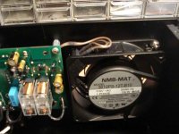
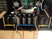
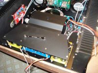
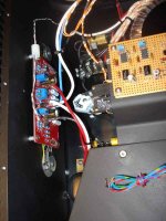
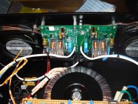
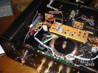
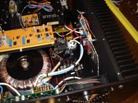
I fabricated the "upper chassis" plate that will hold the vectorboard (with the VU meter, temp monitor, and clipping monitors) and the VU meters themselves, and it's mounted above the capacitor banks. The wiring is effectively completed, except for the vectorboard inputs/outputs and front panel. All circuits tested and "good to go". Other pics show the vectorboard mounted on nylon standoffs, the right-side amp PCB, the left-side amp PCB, the speaker protection PCBs (mounted on the rear chassis plate), the VU meters in a trial-fit on the chassis plate (yeah--they are HUGE!) and then views (from the rear apron of the chassis) of the right amp PCB and bridge rectifiers, and the left amp PCB and the in-rush limiters and bi-stable latching relay. To date, no real surprises, but I must have built this chassis about a dozen times (in my mind, and on paper), before ever cutting any aluminum plate. Fun project!
I fabricated the "upper chassis" plate that will hold the vectorboard (with the VU meter, temp monitor, and clipping monitors) and the VU meters themselves, and it's mounted above the capacitor banks. The wiring is effectively completed, except for the vectorboard inputs/outputs and front panel. All circuits tested and "good to go". Other pics show the vectorboard mounted on nylon standoffs, the right-side amp PCB, the left-side amp PCB, the speaker protection PCBs (mounted on the rear chassis plate), the VU meters in a trial-fit on the chassis plate (yeah--they are HUGE!) and then views (from the rear apron of the chassis) of the right amp PCB and bridge rectifiers, and the left amp PCB and the in-rush limiters and bi-stable latching relay. To date, no real surprises, but I must have built this chassis about a dozen times (in my mind, and on paper), before ever cutting any aluminum plate. Fun project!
Attachments
bbm3......
I suspect--from the laws of probability--that I'm older than you. That just means I've had more time to build things, and make mistakes! In my case, that would apply to both cars and "things with electrons whizzing thru them".
As long as both hobbies give you fun and pleasure--stick with them! I know some of my earlier projects were disasters, and I'm certain your efforts are a WHOLE LOT BETTER than mine were!
Where in Colorado are you?
Ken
In this case the "laws of probability" have been superseded by the "law of reality".
I'm an old fart.
I have way too many hobbies and interests and not enough focus to master any of them.
I live in Colorado Springs as well. Maybe a coffee or beer some time?
Again, very nice builds.
Cheers,
-Bill
I'm an old fart.
I have way too many hobbies and interests and not enough focus to master any of them.
I live in Colorado Springs as well. Maybe a coffee or beer some time?
Again, very nice builds.
Cheers,
-Bill
- Status
- This old topic is closed. If you want to reopen this topic, contact a moderator using the "Report Post" button.
- Home
- Amplifiers
- Pass Labs
- Another F5 build--beautiful music, different drummer