Mr Evil said:Yes, in the Hawksford circuit unity gain is the ideal, but not in this circuit. I have tested such a circuit with a unity gain error amp, and it halves distortion (-6dB). Beyond unity, distortion decreases in proportion to gain.
Right, figures. That's why your circuit is negative feedback, not error correction. EC is a kind of positive feedback.
Jan Didden
Surely that makes Hawksford's circuit NFB not EC too then? Examining Fig4 in J3 from the link you posted, I can see that the error signal fed back via T7 and T1 is -error. Similarly, in the circuit I posted, if the error amp had unity gain, the voltage at its output would be -error (relative to the input).
Yeah, I just thought about something, you had those two 470 ohms summer resistors in your circuit (input to output stage) when you tried it? In that case you would need a gain of 2 for the error correction to be unity.
Edit: Scratch the above. Brain-farth. I was referring to R1, R4 in your post #13. You're loosing some 45dB loop gain there! If you make them equal, you immediately get better specs - you may also get oscillations what with the x 1000 or so IIRC of the inner loop gain.
I would make them equal, and then change the inner loop to a lower value - making it a gain of 2 would pop your eyes - unmeasurable distortion!
That's basically what Bob Cordell did. He applied EC a la Hawksford, but not with an opamp but with two transistors. Your circuit comes much closer to the ideal so you should get very low THD even without the global nfb.
Jan Didden
Argh, now I'm confused. I thought I knew what was going on, now I'm not so sure.
Yes, the resistors are necessary to allow summing at the input, so they must always be present. I made then unequal because it requires less voltage swing from the error amp. With them equal, the error amp goes into clipping while the output stage itself is still several volts away. This is a problem especially with low impedance loads. This also makes me realise that if R1 is infinite, then it becomes a normal NFB system around the output stage.
A gain of two for the error amp with R1 = R4 still doesn't give better distortion than very high gain.
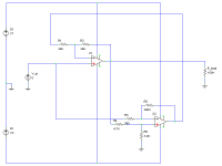
Maybe it will help to see how it works if I attach a schematic of the general concept. X1 represents the output stage in the circuit I originally posted, X2 being the error amp, except it has an overall gain of 2 and feedback is applied to the inverting input of X1 (source-followers don't have inverting input unfortunately, hence the resistors at the input for summing), so the inputs of the error amp are reversed.
Yes, the resistors are necessary to allow summing at the input, so they must always be present. I made then unequal because it requires less voltage swing from the error amp. With them equal, the error amp goes into clipping while the output stage itself is still several volts away. This is a problem especially with low impedance loads. This also makes me realise that if R1 is infinite, then it becomes a normal NFB system around the output stage.
A gain of two for the error amp with R1 = R4 still doesn't give better distortion than very high gain.
Maybe it will help to see how it works if I attach a schematic of the general concept. X1 represents the output stage in the circuit I originally posted, X2 being the error amp, except it has an overall gain of 2 and feedback is applied to the inverting input of X1 (source-followers don't have inverting input unfortunately, hence the resistors at the input for summing), so the inputs of the error amp are reversed.
Attachments
OK, I understand your reasoning. My point was that with R1 = 4.7k and R1 = 27 ohms, from the pov of the main channel opamp there is an attenuator of (grabs his scientific casio) ehh.. -44.8dB (my 45dB guess was pretty good, huh?).
So, making R1 and R4 equal you lose only 6dB both in the main channel and in the EC loop, hence the suggestion of x2 gain in the EC channel.
BTW, did you try to add the EC signal into X4 non-inverting input? That cures the attenuation and probably also the clipping stuff.
But there is another thing, you should get the inputs for the EC loop from the output (OK) and the output stage input. You take that from the wrong point. If you take it from the output stage input, the correction will also diminish the error and you get the error cancellation. The way it is now (I'm still on post #13 btw) you sense the drive signal from the main opamp and that is stationary wrt the error input. Move the non-inverting input feed of X3 to the junction of V4/V5. That'll work.
Jan Didden
The basic circuit, if we take your post # 13 and assume we want to do hawksford EC exact error cancellation looks as attached. You'll see that the gain comes out to 1/2, which is caused by the 6dB loss of the summing network, as expected. But A, the output stage gain has disappeared from the gain equation, indicating that the output stage is completely linearized, and it's output impedance is zero.
In practise, there are of course limits to how equal the two resistors can be, and the gain = 2 accuracy. I tried something similar with one of the resistors as a pot and tuning for max cancellation, but the difference rapidly gets lost in the noise and test equipment limitations.
Jan Didden
In practise, there are of course limits to how equal the two resistors can be, and the gain = 2 accuracy. I tried something similar with one of the resistors as a pot and tuning for max cancellation, but the difference rapidly gets lost in the noise and test equipment limitations.
Jan Didden
Attachments
Well I wanted to include only the output stage in the loop since that makes it easier to obtain stability, plus I was thinking of creating a self-contained near-perfect output stage that I could use for experimenting with amp topologies (just stick it on the end of whatever I'm working on).janneman said:...BTW, did you try to add the EC signal into X4 non-inverting input? That cures the attenuation and probably also the clipping stuff...
It's interesting to see how moving a wire or two can make such a difference. Simulations suggest that distortion is very similar to my version (if only I had enough money, I would buy a distortion meter and compare them in real life too), which is sort of disappointing. Other characteristics aren't so good, e.g. the input impedance is low unless the summing resistors are very large.janneman said:The basic circuit, if we take your post # 13 and assume we want to do hawksford EC exact error cancellation looks as attached...
Nice discussion about EC basics from Mr.Evil and Janneman
Mr.Evil,
Janneman,
I have a question about Hawksford EC when headed to classAB (not classA) output stage. ClassAB output stage has one major drawback, that is Xover switching distortion (because in AB pushpull output stage, the transistors only working half the signal, so in AB or B there always xover distortion)
Does Hawksford EC can fix this/ remove (or reduce) class AB Xover distortion, or not? Or Xover distortion cannot be fixed by Hawksford EC (needs something like Blomley cct)?
Mr.Evil,
Your idea of opamp EC can be added to whatever amplifier with unity output stage (EF). With help of floating +/-15V and a few resistors offcourse.(just stick it on the end of whatever I'm working on).
Janneman,
I have a question about Hawksford EC when headed to classAB (not classA) output stage. ClassAB output stage has one major drawback, that is Xover switching distortion (because in AB pushpull output stage, the transistors only working half the signal, so in AB or B there always xover distortion)
Does Hawksford EC can fix this/ remove (or reduce) class AB Xover distortion, or not? Or Xover distortion cannot be fixed by Hawksford EC (needs something like Blomley cct)?
Mr Evil said:
Well I wanted to include only the output stage in the loop since that makes it easier to obtain stability, plus I was thinking of creating a self-contained near-perfect output stage that I could use for experimenting with amp topologies (just stick it on the end of whatever I'm working on).[snip]
Yes you are right. In hindsight, I realise that using the + input of X4 only works with the gain of X4=1 or by correcting for the gain of X4 in the EC loop.
The idea to use this as a stand-alone output stage is a very good one! You must have been reading my mind
Mr Evil said:[snip]It's interesting to see how moving a wire or two can make such a difference. Simulations suggest that distortion is very similar to my version (if only I had enough money, I would buy a distortion meter and compare them in real life too), which is sort of disappointing. Other characteristics aren't so good, e.g. the input impedance is low unless the summing resistors are very large.
Are you kidding? Changing a wire can make or break it. You really need to fully understand it, then it all falls in place!
But really, the THD must go clearly down if you get all the factors right. I did a simulation with an output stage consisting of power transistor models in my sim but used an ideal amp block for the correction amp. The THD went down to -180dB, probably the numerical limit of my sim. The output stage just disappears from the scene as far as distortion goes. Not in practise of course, but this was a good way to show the validity of the concept.
And I wouldn't worry about the Zin at this point. You can always scale the summer, and you will drive this thing from a low Zout or buffered stage anyway, wouldn't you?
Jan Didden
lumanauw said:[snip]Janneman,
I have a question about Hawksford EC when headed to classAB (not classA) output stage. ClassAB output stage has one major drawback, that is Xover switching distortion (because in AB pushpull output stage, the transistors only working half the signal, so in AB or B there always xover distortion)
Does Hawksford EC can fix this/ remove (or reduce) class AB Xover distortion, or not? Or Xover distortion cannot be fixed by Hawksford EC (needs something like Blomley cct)?
Luminauw,
The Hawksford EC corrects for any non-linearity in the output stage, that is, at any time the output would deviate from exactly following the input, it is corrected.
Now there are a few limits of course. For one thing, the output stage must be physically able to drive the load to the required level. if not, the EC loop will have a large error output but the output will not be correct.
Secondly, if you look to my figures above, there is an implicit mathematical assumption which is that there is a relation between Vo and Vx through the gain A. That means that when A = 0, all bets are off. So, a class AB will be OK, but if you bias the output stage in such a way that both halves are off at a certain point, A=0 and the EC cannot fix that.
In addition, Hawksford recommends to limit this concept to EF output stages where the gain is already close to 1, so the EC is relatively easy. It took me some time to pick the significance of this up. The reason was, I think, that he had in mind to do the EC with the components that are already present. In his examples, and also as later proposed by Cordell in his EC mosfet amp, they use the transistors for the bias setting to double as EC amplifiers! This is extremely smart, and from an engineering point most creative: Use the same components, but get a totally different - and much improved - result. There are some VERY clever people out there!
But, in theory, there is nothing to stop you designing an EC stage enclosing a stage with a gain other than 1. You just have to make sure that the additional requirements to output a correction signal are taken care of by the EC loop. The two bias transistors are then no longer able to take care of it. As shown in my two figures posted above, the math is extremely simple and elegant. Hawksford paper is more difficult to read, but he got paid for it I guess...
Jan Didden
Edit: see attached for a gain of 2 EC stage.
Attachments
ingrast said:Off topic but related.
Jan:
Did you receive my mail of yesterday in relation with this subject?
because of a server failure here for the last hours I am not receiving mail though I can send.
Let me know here if you dont´t mind please.
Rodolfo
Yes, and agreed. You should get reply.
Jan Didden
janneman said:
Yes, and agreed. You should get reply.
Jan Didden
You have mail
Rodolfo
That's exactly what I mean. It's like music: There are only a limited number of components (notes) to use, but they can be arranged in an infinite number of combinations, and moving just a single one makes the difference between concord and discord. Sometimes it takes a leap of logic to make a simple change, like the invention of negative feedback itself.janneman said:Are you kidding? Changing a wire can make or break it. You really need to fully understand it, then it all falls in place!
Mr Evil said:
That's exactly what I mean. It's like music: There are only a limited number of components (notes) to use, but they can be arranged in an infinite number of combinations, and moving just a single one makes the difference between concord and discord. Sometimes it takes a leap of logic to make a simple change, like the invention of negative feedback itself.
Very true. Even with a lot of experience, one can sometimes make a mistake in the interpretation of a circuit detail because it looks just like something you know, and the subtle change that makes it totally different eludes you. Your example of music is a good one, except that I think that a musician would immediately spot the subtle change - or would he?
Jan Didden
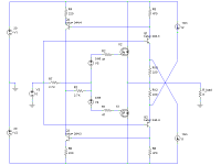
Mr Evil said:Refelcting on this, and lumanauw's question about a discrete version, I modified on of the Hawksford discrete error correction circuits to change it to my method.
It all looks pretty standard and really misses a lot of the
virtues of the Hawksford circuit which are that that error
circuitry is constrained voltage wise "inside" the OP stage.
IOW there is very low voltage modulation of the error
correction bjt's which is a good thing for a) speed and b)
linearity.
Once you start referencing the voltage rails with current
mirrors and such, there are many ways to do it and you may
as well just use a CFP at the OP pair.
Have you checked if this circuit is stable or needs any HF
compensation?
Cheers,
Terry
- Status
- This old topic is closed. If you want to reopen this topic, contact a moderator using the "Report Post" button.
- Home
- Amplifiers
- Solid State
- Another error correction output stage.