0.5 = 24 AWG 0.8 = 20 AWG I THINK YOU HAVE GOT IT RIGHT AWG conversion table
I THINK YOU HAVE GOT IT RIGHT
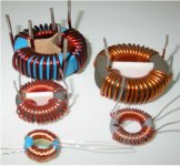
the coils are opposite one another as photo show?thank you") can kindly make a pencil drawing?
can kindly make a pencil drawing?
I THINK YOU HAVE GOT IT RIGHT
the coils are opposite one another as photo show?thank you
can kindly make a pencil drawing?Attachments
A 2 ohm to 4 ohm impedance conversion will require a Turns ratio of 1:1.414 not 1:2.
Impedance transformation is the square of the winding ratio.
Or "Impedance ratio" = "Turns ratio"^2 .
If you use a 1:2 turns ratio then your reflected impedance will be 8 ohms not 4 ohms, In which would be okay too!!
jer
P.S. Yes, Using resistors work in a pinch to protect your amplifier, But they do nothing but waste precious power and attenuate the peak SPL that the driver could possibly produce.......Ohms Law!!
Last edited:
It is an even bigger deal when your ribbon is only .1 ohms or so then your losses will 90% with just using a 1 ohm series resistor and it will be 99% using a 10 ohm one.
The biggest issue about using a transformer is choosing the proper material core type and size and then calculating the correct amount of primary turns so that your core doesn't saturate at the lowest frequency of operation for whatever your peak operating voltage level would be.
This is only a concern for the lowest frequency of operation and does not apply as the frequency goes up.
As ribbons don't have any significant amount to inductive and/or capacitive reactance they are considered to be purely resistance.
Because of this there aren't any real complications of resonance peaks and such as compared to ESL with transformer+panel capacitance's and transformer leakage inductance.
To do the nature of such a design any of the resonate peaks that there are will be much much higher than that of the audio band.
This is true even for the common Torrid power transformer cores I have tested so far that have a large amount of self capacitance.
Resonance's are typically above 50Khz to 100Khz and even as high as 600khz for some of the ones I have on hand.
For frequency's above 1Khz have a hard time detecting any added THD due to the transformers core at low to moderate power levels with my 24bit sound card that is rated to at least .005% to .002% THD.
I have shown these results several times but they can be found here,
A TEST JIG FOR FINDING ESL STEP-UP TRANSFORMER PARAMETERS
Keep in mind that I was using a Crown DC300A for these tests at full power and the THD levels are typically that of the amplifier it self at those levels.
At 1 watt they were immeasurable with my setup and I got typically .005% across the whole band above 500hz to 1Khz or so.
These tests were also done with my motherboard sound system and this accounts for any glitlching and abnormalties you see on the charts.
I have re-done these tests using my better sound card (Gina24) and the results are much more impressive than those in the charts I have shown.
But the data is still very similar but the charts are cleaner.
I will re do this again sometime when time is available just for the record to show the correct results.
Cheers!!
jer
Last edited:
Here is a Great chart that I just found on some of the more common Toriods that you find that are color coded.
http://skory.z-net.hu/alkatresz/porvas_gyurumagok.pdf
The Yellow/White on in post #780 should be a Material type 52 and is one of the highest permeability types in the list and this is what you want to use as #26 is another one as well.
I haven't experimented with these types of cores for the audio range very much yet, But I did use a Yellow/White core (#52?) for my homemade magnetometer and it worked Great!!
http://www.diyaudio.com/forums/plan...transformer-ribbon-tweeter-2.html#post2504316
I hope this helps.
jer
Last edited:
You guys are focusing on Sensitivity , my comments were regarding SQ. If drive and impedance matching is the goal then yes to transformers, my experience have shown the resistor is best for sound quality, especially if you don't have to get above 2 ohm easy to achieve if doing multiple traces.
Have you guys done any comparisons R vs Trans..?
Have you guys done any comparisons R vs Trans..?
No I haven't yet, I did use a resistor on my very first one and them.
I gave up because I didn't have one with a high enough power rating to be of any use.
Then I started building ESL's and never turned back.
But even in that experience, I rarely have any SQ issues if the transformer is sized properly.
Being that ESL's are powered by transformers this raises the same questions as well.
I have done quite a few measurement to try and detect any THD issues and haven't run across anything major except for core saturation at the lower frequency's.
This is something that many don't understand and all that they do know is how the transformation ratio works.
Then they make one and wonder why that it doesn't sound good.
I have been there myself!!
Just like using a resistor will protect your amplifier from the low impedance if it can't deliver high currents.
But by the same token, The SQ can drop as well because you now have to run the amplifier at a higher level towards clipping to reach a certain level of SPL that is comfortable due to the power wasted in the resistor.
200 watt resistors aren't exactly cheap either considering the amount of power loss you get going to the driver.
But then again exotic core materials to get extremely low THD's aren't cheap either and at best they are only good for the higher frequency's anyhow.
But I do understand your point.
Jer
I run 4(parallel /R) heat sinked per side, they barely get warm, so heat is never an issue , saturation is never an issue , bandwidth is never an issue and they cost far less than any transformer i priced out, i do keep the overall R value at 1 ohm max for a 2:1 ratio. Amplifier faces 1.5 , best compromise for drive an SQ so far ...
Drive the ESL DIRECT and never look back ...
I know the 57 guys have tried moving away from the original Quad transformer and had to run back , so differences abound ..
Drive the ESL DIRECT and never look back ...
I know the 57 guys have tried moving away from the original Quad transformer and had to run back , so differences abound ..
Last edited:
I was just talking to a friend that is working on his DIY ribbon and I found the video of one that is 2" wide and I think was in these threads as well.
But many of the links to those pictures are now defunct.
And if I recall it was once mentioned that he was using a massively paralleled chip amp to drive them.
But he never elaborated on the design of the amp itself.
Something like this had been on my drawing board for quite some time.
Here is the link to the video I had just found a moment ago,
Diy Ribbon Tweeter prototype - YouTube
Direct Drive ESL's?!!!!!!
Ohhhh Yah, I finally have the FET's I needed to get to get started that project!!
Cheers!!
jer
I found it!!!
Here is the video that shows the massive 18 chip, chip amplifier on the floor!!
Not the same ribbon as in the last post though.
Diy Ribbon Tweeter prototype - YouTube
jer
Here is the video that shows the massive 18 chip, chip amplifier on the floor!!
Not the same ribbon as in the last post though.
Diy Ribbon Tweeter prototype - YouTube
jer
Last edited:
primo test ribbon tweeter
This is the first test seems ok as a response https://www.youtube.com/watch?v=Hwyff5kyFeQ&feature=youtu.be
This is the first test seems ok as a response https://www.youtube.com/watch?v=Hwyff5kyFeQ&feature=youtu.be
The two most common ribbon designs are (1) magnets form ribbon gap; and (2) iron pole pieces form ribbon gap. Due to the brittle nature of magnets from high temperatures used in formation, most magnets have slightly irregular surfaces and will vary slightly in thickness across samples. Hence, machining iron pole pieces with adjustments to set the gap offers the tightest gap tolerance. Since iron saturates around 1.7T, using iron pole pieces to set the ribbon gap with todays super NdFeB magnets can limit the maximum magnetic field in the gap to a lower level than the topology where the magnets face each other to create the ribbon gap. If you look at Dhenry's ribbon pictures in this thread you can see how irregular the magnet edges are relative to machined steel.
There are design methods to reduce gap distortion when super tight tolerances cannot be achieved, but these are typically manufacturing secrets.
Doing some research on ribbons and I'm finding lots of little gems of information in this old thread. Can anyone describe the geometry of (2) in more detail where iron pole pieces form the gap. Where are the magnets arrayed in this case? What are the geometries of the iron pole pieces?
Dan
Neodymium magnets have very flat surfaces, so no problem with that, and I don't think that the iron part that holds them actually makes the field any stronger in the gap. Don't put any steel in gap part. I use the iron channel to hold them since it is the easiest way to do it. No glue, just copper pegs to hold them at the outer edge of channel. Use Grade N52 magnets
- Status
- This old topic is closed. If you want to reopen this topic, contact a moderator using the "Report Post" button.
- Home
- Loudspeakers
- Planars & Exotics
- Another DIY Ribbon thread