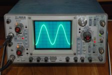
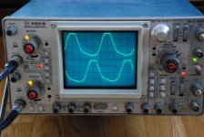
And finally the same wave after adding both signals. Here we can see the strange shape at the output.
The asymetrical clipping that can be seen in the previous picture could be causing this behavior but then, why is only happening with high frequencies (10-20KHz) and not for 1KHz?
Thanks for your help.
Xavier
The asymetrical clipping that can be seen in the previous picture could be causing this behavior but then, why is only happening with high frequencies (10-20KHz) and not for 1KHz?
Thanks for your help.
Xavier
Attachments
Hi,
I´ve noticed the same problem in my AlephJ-X thread. It always happens when there´s current limiting (in my case only at 4 ohms).
Did you notice that there´s a build in time factor?
The signal is ok for a second or two and then goes into severe distortion. I think it has something to do with the bootstrap capacitor losing it´s load and the two resistors connecting it to the rail and the bjt.
It got worse when lowering the value of the upper resistor (connected to the rail). I will experiment further when my Jfet input is ready.
William
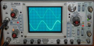
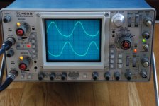
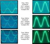
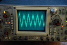
The following image summarizes three cases (1KHz, 20KHz and 20KHz. All measured using an 8R wirewoud resistor between
out- and out+, but was the same for 4R and without load)
1 and 2: Normal behaviour
3 and 4: for high frequencies, the positive part of the wave is thiner and taller than the negative. This gets hidden in pict 4 since one side compensates the other.
5 and 6: If we increase the output level, the amp goes into clipping at the positive way before than the negative since the wave is much taller at the positive.
So the problem seems to be the behavior in high frequencies.
Xavier
Attachments
posted by Wuffwaff
I´ve noticed the same problem in my AlephJ-X thread. It always happens when there´s current limiting (in my case only at 4 ohms).
Did you notice that there´s a build in time factor?
The signal is ok for a second or two and then goes into severe distortion. I think it has something to do with the bootstrap capacitor losing it´s load and the two resistors connecting it to the rail and the bjt.
It got worse when lowering the value of the upper resistor (connected to the rail). I will experiment further when my Jfet input is ready.
William,
I think the problem could be similar. Not sure I understood what you are refering to when mentioning "build in time factor" though.
The two resistors connecting the rail, cap and bjt I am using are 520R for the upper (R14 in original schematic) and 1k for connecting to the bjt (R15). The "high-powered" version uses 1.5k and 1.5k. Do you think that using these values could improve things?
(note that my rails are aprox. +/- 17,6v).
Hi,
with time factor I mean that first the signal is OK for a second or two and then suddenly goes into distortion.
Just try to set it at a level where it just distorts and then turn off the signal generator, wait a few second and turn it on again.
In my case the signal will then be OK for a few seconds , then return to it´s distorted form.
I´ve used 1k2 / 1k2 and changed this to 1k5 / 1k5 wich was a bit better.
Looking at older Alephs (2, 4, 5) the upper resistor is even 4k75
William
William,
May I suggest you try taking out the 2 resistor and replace the cap with a 9V battery ? The experiment will cost you 2.50 Euros at most (and an hour or so for testing).
You would probably need to trim the CCS again because of the difference in voltage (across what was the cap).
Patrick
May I suggest you try taking out the 2 resistor and replace the cap with a 9V battery ? The experiment will cost you 2.50 Euros at most (and an hour or so for testing).
You would probably need to trim the CCS again because of the difference in voltage (across what was the cap).
Patrick
I use 1.5k/1.5k for r14 r15, with 12 fet for channel, rail voltage +21-21 and 6 amp. bias... and I have the same problem that xavier.
In your test, have you used a balanced signal test? I used unbalaced signal test.
Thank Paolo
p.s. with pspice I can't see any of these distortions.
In your test, have you used a balanced signal test? I used unbalaced signal test.
Thank Paolo
p.s. with pspice I can't see any of these distortions.
Some progress
Today, while I was I checking this ...
Today I checked this and I found that the wave was not OK from the first second. So, it seems to be a different problem.
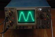
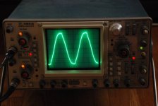
But, while I was checking with the scope I discovered a 2MHz/100mV amplitude oscillation. The attached image shows this wave when connecting the probes between the 100k feedback resistor and gnd.
So, the problem I am facing could be produced by an oscillation. This could explain why Sinosuko, who is using the same PCB, is facing the same problem.
I did the following:
1- I moved the 68R resistors to ground from the back of the pcb to the output connectors to minimize loops at the output. No changes
2- I increased the feedback caps from 10pf to 20pf by adding one 10 pf cap in parallel. I could not detect any change
3- I added one 2.2n cap between base and collector of each CCS bjt (BC550C). Bingo! Now the wave at 20KHz has improved a lot. The shape is normal until Vpk=30v. The oscillation has been reduced about 25%, but it is still there.
One thing that I detected from step 2 (I didn't checked before) is that the oscillation is not present immediately when I switch on the amplifier. It starts after about 15min suddenly.
I might try with a bigger cap tomorrow.
Xavier
Today, while I was I checking this ...
Originally posted by Wuffwaff
with time factor I mean that first the signal is OK for a second or two and then suddenly goes into distortion.
Just try to set it at a level where it just distorts and then turn off the signal generator, wait a few second and turn it on again.
In my case the signal will then be OK for a few seconds , then return to it´s distorted form.
Today I checked this and I found that the wave was not OK from the first second. So, it seems to be a different problem.
But, while I was checking with the scope I discovered a 2MHz/100mV amplitude oscillation. The attached image shows this wave when connecting the probes between the 100k feedback resistor and gnd.
So, the problem I am facing could be produced by an oscillation. This could explain why Sinosuko, who is using the same PCB, is facing the same problem.
I did the following:
1- I moved the 68R resistors to ground from the back of the pcb to the output connectors to minimize loops at the output. No changes
2- I increased the feedback caps from 10pf to 20pf by adding one 10 pf cap in parallel. I could not detect any change
3- I added one 2.2n cap between base and collector of each CCS bjt (BC550C). Bingo! Now the wave at 20KHz has improved a lot. The shape is normal until Vpk=30v. The oscillation has been reduced about 25%, but it is still there.
One thing that I detected from step 2 (I didn't checked before) is that the oscillation is not present immediately when I switch on the amplifier. It starts after about 15min suddenly.
I might try with a bigger cap tomorrow.
Xavier
Attachments
Xavier,
This comes from Nelson himself, written somewhere in the big AlephX thread:
/Hugo
This comes from Nelson himself, written somewhere in the big AlephX thread:
0.001µF RF compensation caps can be added between Collector and Base of Q3, Q8 or 0.01uF caps between Collector and Emitter of the same transistors.
/Hugo
I've been doing some more testing to remove the 500KHz oscillation (yesterday I mentioned 2MHz by mistake):
1- First of all I removed all the compensation caps I added yesterday and changed the two drain resistors from 520R+1k to 1k+1.5k. This should decrease the current going through the bjt and change the frequency characteristics. It might get rid of the oscillation without any additional cap.
The result: the oscillation was there and the shape of the 20KHz wave was bad again.
2- Added a 10n compensation cap between emitter and collector of the two bjt's. Result: same as before.
3- Removed the 10n caps and I put 1n cap between base and collector. Results: great improvement in the 20KHz sinus wave but the oscillation was still there.
4- I tried with 2.2n and 4.4n and the sinus wave was getting worse and the oscillation was still there.
5- Then, tried 150p. This got rid of the oscillation and the 20KHz is like case 3. It is almost perfect until an amplitude of 30v
So I will leave this channel with this configuration for some days to check how it sounds.
BTW I had to readjust everything, even the AC Gain (now it's 50,4%)
Xavier
I checked for oscillation but I did't found anything. I can see aoly the "bad distortion" at high frequency (>10khz).
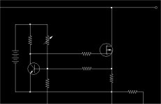
After Xavier suggestiom, i tried to put a cap between B-C of q3 and q8 (Grey Rollins schematic), 3.3nf and the sinus wave is quite better, (no improvement with the cap between E-C), I'll trie with othe cap but (lower) but today :
I have the time but the shop are CLOSED
Paolo
After Xavier suggestiom, i tried to put a cap between B-C of q3 and q8 (Grey Rollins schematic), 3.3nf and the sinus wave is quite better, (no improvement with the cap between E-C), I'll trie with othe cap but (lower) but today :
I have the time but the shop are CLOSED
Paolo
- Status
- This old topic is closed. If you want to reopen this topic, contact a moderator using the "Report Post" button.
- Home
- Amplifiers
- Pass Labs
- Another Aleph X up and running