jlsem said:"Please see RDH, pages 199-203."
I swiped this from another thread.
John
Or even;
http://www.audioxpress.com/resource/audioclass/ga300ac.pdf
and
http://www.audioxpress.com/resource/audioclass/ga400ac.pdf
Yves.
poobah said:You are talking about a method for PP analysis though, and I would like to learn more. I'm having trouble following why the impedance changes. You are talking about the effects of primaries driven simultaneously and a non superposition way of looking at the circuit?
If you look at class A PP as a balanced source then it might make sense. jlsem is right; it's not really that simple because rp varies with signal, so they don't make a truly balanced source. But it's a good simplification because it makes the analysis A LOT simpler.
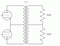
Anyway, consider a 1:1 PP transformer. Put 1000 ohm resistors across each half of the secondary. Since it's a 1:1 transformer the plate to plate load seen at the primary is 2000 ohms.
Now ask yourself the question: what load is seen across each half of the primary? Seems obvious by inspection that it must be 1000 ohms. It's a 1:1 transformer; the same load that's across each half of the secondary must appear across each half of the primary. That's 1/2 the plate to plate load.
If you drive only one side of the primary then you have a 1:2 voltage ratio which is a 1:4 impedance ratio. In that case the load seen would be 1/4 * 2000 ohms = 500 ohms. 1/4 plate to plate.
Incidentally, it's not hard to prove using conservation of energy. Since it's a 1:1 transformer the same currents and voltages must exist at both the primary and secondary. If the tubes each saw 1/4 the plate to plate load in class A then there would be a different amount of power going into the transformer than coming out. In fact, IIRC (it's been a while since I proved it to myself) you'll get different calculated powers depending on whether you use i*v, v^2/R, or i^2*R.
OTOH, when driving only one side (pure class B, if such a thing existed) then the power calculations work out ok at 1/4 plate to plate load.
-- Dave
Attachments
Thanks Dave,
We were really talking apples and oranges... I didn't realize at first they we were talking about an "effective impedance" as a result of a compound analysis rather than a superposition type.
I'm itching to build a PP tube rig... if I can design or purchase OPT's that truely thrill me.
Funny you mention energy calcs... I am always using energy calcs to solve stuff. Crunch tricky stuff in a hurry and avoid all that Simulation and Laplace ****. One of these days I'll fork out for Mathematica and let it crunch instead... in the meantime, spreadsheets...
We were really talking apples and oranges... I didn't realize at first they we were talking about an "effective impedance" as a result of a compound analysis rather than a superposition type.
Effective impedance is the same as the impedance seen by each tube in a push-pull scheme, which is the term I used in my post, for which I got hammered. Not apples and oranges.
Nice try,
John
- Status
- This old topic is closed. If you want to reopen this topic, contact a moderator using the "Report Post" button.
- Home
- Amplifiers
- Tubes / Valves
- Anode loaded 6080 giving less than unity gain, Why??
