Hi Dd,
some mods on your last posts - What do you think?
but to go further I have to know what kind of tools you have, or service used
During WE, I've started turning the first parts of Syrinx (and of 3point, and of a "improved unipivot": the cleaning of the garage from chips takes more time than making parts ...), hope in a month or two to post the real arm (finally)
Carlo
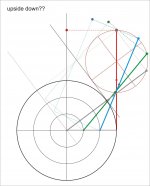
Walter. I turned it upside down - maybe too much, what a mess!
some mods on your last posts - What do you think?
but to go further I have to know what kind of tools you have, or service used
During WE, I've started turning the first parts of Syrinx (and of 3point, and of a "improved unipivot": the cleaning of the garage from chips takes more time than making parts ...), hope in a month or two to post the real arm (finally)
Carlo
Walter. I turned it upside down - maybe too much, what a mess!
Attachments

Is it servo driven?
No, it is purely mechanical.
If we can have almost zero friction (P) Horizontal bearing the stylus drag will move the wand forward and so the disc. Anti skate can be arranged like conventional tonearms and I guess the anti skate mechanism will keep tonearm tangent to the grooves. (Imagine anti skate and stylus drag working together)This arrangement is not self-aligning, stylus drag will pull the arm off-tangent (and then it will also skate). You need to provide an opposite force to stylus drag.
Regards.
# 1501 -- part 2
Dd : But a string can only pull but not push and when encountering eccentric record, will the string go slack? And when it gets to end of record will the horizontal rocking be dangerous to the stylus? Will a magnetic damping a la Dynavector style help?
I know almost nothing about Birch tonearms, could it work?
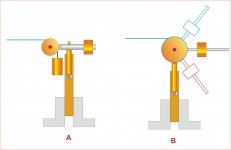
Solution A works like those of stringed Thales - a (swiveling) pulley and a small counterweight
Solution B works like micro seiki proportional antiskating: pulling of the string it can increase (or decrease) the action
This way the string would'nt slack, and the cartrige gets a bit of protection from damage
If, instead, everything needs to be rigid and fixed lengths, look at these (all size available)
Testa sferica Metallo, Plastica con filettatura interna M3 32 mm Reely 1 pz. in vendita online - HY023-00510 | Conrad
Dd : But a string can only pull but not push and when encountering eccentric record, will the string go slack? And when it gets to end of record will the horizontal rocking be dangerous to the stylus? Will a magnetic damping a la Dynavector style help?
I know almost nothing about Birch tonearms, could it work?
Solution A works like those of stringed Thales - a (swiveling) pulley and a small counterweight
Solution B works like micro seiki proportional antiskating: pulling of the string it can increase (or decrease) the action
This way the string would'nt slack, and the cartrige gets a bit of protection from damage
If, instead, everything needs to be rigid and fixed lengths, look at these (all size available)
Testa sferica Metallo, Plastica con filettatura interna M3 32 mm Reely 1 pz. in vendita online - HY023-00510 | Conrad
Attachments
some mods on your last posts - What do you think?
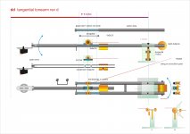
Nice drawing, Carlo! I like the slim style design. The detachable vertical arm from the magnets is a nice touch. However, the string needs to be attached to the midpoint (center of rotation) of the axle, the back magnet gets in the way. I would use three spherical magnets, one front, two back, so the string can be tied to the axle. And the three magnets allows for azimuth adjustment for the vertical arm. The front end of the rods need to be connected so you won't ring like a tuning fork and perhaps we can implement an arm holder there. Keep tweaking!
Carlo, I think I like how you have the magnets but have to drop the entire veryical arm assembly just an inch lower from the horizontal bars so the back magnet is clear from the string tie point. My previous arrangement of 3 magnets makes changing arm requiring azimuth readjustment every time, not convenient. The front of the rods should still be connected.
Easy mods, Dd - sorry, the wrong string point was a bad mistake!
yes, if you use spherical magnets the sub-arm is allowed to roll (not so good! the azimuth can be regulated once, and for that cartridge, with the headshell - shaft screw ) - this new solution (magnets on sub arm) for clearing the string hooking may work without lowering more the arm from it's pivot (not so good!)
Added the front connection too, but maybe you under evaluate how the carbon is strong (and dull adds someone, not me)
I've designed this easier plexy version: tools needed just a small circular saw and a drill press (+ some skill)
carlo
slim design: not italian style, simply trying to have low masses...
doubt - near magnets may alter low current signals? i don' think so, but will ask my son..
Attachments
Easy mods, Dd - sorry, the wrong string point was a bad mistake!
doubt - near magnets may alter low current signals? i don' think so, but will ask my son..
The string has to be the midpoint of the axle, vertically and horizontally. See picture below.
Maybe we have to be careful about the magnets affecting the tiny signal wires, especially threading through magnet holes.
If I dispense the idea of removable armwand, I would simply implement something like this clamping system that allows for azimuth adjustment.
The front connection between the rods should be above the vertical arm and can be used as arm holder. Maybe some flip-able magnet?
Happy tweaking!

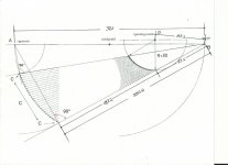
Can anyone tell distance involved in Birch geometry ? That is...
(A) Spindal to (P) Guiding Pivot
(P) to (B) Pivot
(D) Thread fix pivot on Wand to (C) Stylus Point.
Thanks.
(A) Spindal to (P) Guiding Pivot
(P) to (B) Pivot
(D) Thread fix pivot on Wand to (C) Stylus Point.
Thanks.
string - yes of course Dd - Damn, i've moved down the arm in drawing, but not the string toghether; It's a mistake not a mod, difficult to tie it to a rolling bearing!
But what happens at the other end of the string, at guiding point? info needed
magnets - a permanent field influences electrons in a gas, not in a copper connector (they must move only from one atom of copper to another). So the only concern is to fix the wires, because - in theory - the variable field generated by the signal could make them vibrate (attraction - repulsion towards the magnet).
azimuth - that system seems heavy, if made in the position where we have to put it (> hor. eff. mass)
connection - good idea, that can be made also from that position (eg. with an eccentric clip) but same perplexities as above. My idea, since there is no lifter, was to prevent the stylus from plunging on the plinth
carlo
Hi DD,
I fear that your current design is going to suffer from lateral instability where the vertical arm rests on the two round rails. I think that the contact points in the grooves in the bearings are not going to be sufficiently rigid to prevent any lateral rotation at this point. (The groove will allow a little rotation before rolling) Any play in the bearings will also allow a small amount of lateral rotation. I would also recommend against ball race bearings if at all possible due to the aforementioned chatter.
Niffy
Can anyone tell distance involved in Birch geometry ? That is...
(A) Spindal to (P) Guiding Pivot
(P) to (B) Pivot
(D) Thread fix pivot on Wand to (C) Stylus Point.
Thanks.
Hiten,
Since the spindle to platter rim distance is 152.4 MM, I found the scale of the drawing to an actual platter is 1-1.3 and got the other numbers from that. I think the measurements are accurate or close.
With a smaller Thales A - B diameter , the arm B - C could possibly be as short as 200 MM before the guiding pivot P is too close to the platter. 280 mm is a good tonearm length, but if you want a longer one, just make the A - B diameter larger. A birch design much larger than 280 mm will need a large plinth. Once the Thales circle size and guide pivot position are chosen, the rest is determined by the geometry.
Attachments

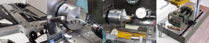
Meanwhile:
measuring & cutting, measuring & turning, measuring & drilling, measuring & threading, measuring & measuring ...
Just two or three (hundreds?) parts prior finishing. polishing, assembling, cabling ...(and testing!). I'll let you know.
ciao - carlo
PS - thanks to this thread and to all those who. with their ideas. gave me the desire to experience again: my lathe was sleeping from too long time
Attachments
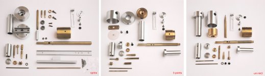
Hopefully Doug.
The unipivot should be more comfortable to use than the one made ten years ago; no problems for building, but was a known territory. For the 3 Points the difficult thing was to make the balls holes in the mobile part fit perfectly with the circular rail (it's a matter of few thous). I'm impatient to hear it, because now that it only leans on two points (the third is the stylus) behaves like a suspended arm, which is not at top of my wishes.
Syrinx: gadget tests are encouraging (I adopted the unique pulley you had invented, but with two grooves), very low friction. Building the linear bearing with my tablesaw was a real nightmare: the idea of using two wire rods like in many products was unuseful (flexing) so I returned to the brass guide: 2x3mm with a centered groove of 1 mm (picture of a test). In the past i've built a 6x17cm panoramic film camera for my work, but now maybe I'm ready for cuckoo clocks!
Now waiting for my metalshop to get me the 15x15mm bar I need to finish it all.
hello and thanks again for advice and analysis. Carlo
One day I'll write a off-off topic post dedicated to "If only" and generally to those who think that experience and precision can be bought: the early years with my minilathe were a hard lesson of humility.
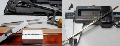
Attachments
Carlo,
You made those channels with a table saw? I don't think I have the nerve to try that. Do the balls ride on the inner edge of the channel walls?
A college near me offers machining classes and friends have offered me use of their mills and lathes, but so far I've not done anything. I don't doubt that learning to use your mini lathe took time, but I envy you that skill.
I'm pleased that my single pulley suggestion was helpful. I every much want the Syrinx to be successful.
Any further progress?
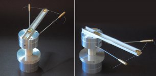
Yes, that in the picture: a small table saw built many years ago, very precise - then there was nothing like that to buy, and maybe not even now. A friend has the Proxxon, but it is designed for wood, not for metals.
Better using friends than their machines, to learn quicklier!
There is some progress, but as you know, this is the stage where all the errors or inaccuracies occur: the string gadget works really fine, in fact the friction is just that of the two (thanks!) ball bearings, because the string has no movement.
Problems maybe will come from the linear bearing: the balls flow very well into the grooves, but the tolerances are tight, and the register screws will be crucial.
Now, having no mill (and no intention of buying one) I have to wait the 15x15 bar to end the Syrinx: in the meantime I'm fighting with "3 Points".
Ciao - carlo
I'm afraid these chats can only interest to diyers like us, and to be completely off topic
Attachments
- Home
- Source & Line
- Analogue Source
- Angling for 90° - tangential pivot tonearms