Welcome back Adelmo and Consty. It's good to see a spark in this thread again.
Consty, I'm glad you posted your mathematical solution to Frank's curve again. I didn't think it got the attention it deserves when you posted it before.
Adelmo, I posted a mechanical way to get the curve back at #842 on page 43. The idea about how to do that was generously offered by Frank Schroeder. I tried to move the photo here, but that didn't work. Maybe someone else knows how.
I built a successful clone of Frank's PLT, but didn't post it because of possible IP problems at that time. It wasn't very sophisticated, but it did track accurately and allowed the cartridge to produce very decent music.

Found it. A pencil lead will work, but a trail of points made a something sharp like a small nail works better.
Doug
Consty, I'm glad you posted your mathematical solution to Frank's curve again. I didn't think it got the attention it deserves when you posted it before.
Adelmo, I posted a mechanical way to get the curve back at #842 on page 43. The idea about how to do that was generously offered by Frank Schroeder. I tried to move the photo here, but that didn't work. Maybe someone else knows how.
I built a successful clone of Frank's PLT, but didn't post it because of possible IP problems at that time. It wasn't very sophisticated, but it did track accurately and allowed the cartridge to produce very decent music.
Found it. A pencil lead will work, but a trail of points made a something sharp like a small nail works better.
Doug
Hi Doug,
Yes, I fully agree with you about the chart calculation posted from Consty, it is a kind of genial of him too and deserved more attention.
Regarding the mechanical way you have posted for which I thank you, was a similar way I was following up, but I did not understand before that the cart was still making a kind of curve. Consty told me that with this system I could not achieve it as this TA it is not exactly like the real linear type with linear track guides.
Now I understand a bit more on how this TA is working and as I am resuming the project. Also I am taking out from the garage the old Lenco not used ( modify the standard plinth for this TA ) as I think this genius TA it is better fitted on a non floating TT.
By the way for the vertical motion of the TA I was thinking something similar to the Supratrack TA ( like an Unipivot but with 2 pivot working in the horizontal plane and not in vertical )
Thank you all and best regards.
Adelmo
Last edited:
Adelmo,
I just looked at the Supra again and understand it better. Although I like that design, I would hesitate to use it for my first attempt at a Schroeder PLT because the trailing control arm with the magnet and the forward movement the swing arm introduce complex forces. It's very important to make sure the V and H axes are carefully aligned to each other and gravity. My suggestion is to make things as simple as possible by using a conventional bearing arrangement and then add complexity.
Doug
Hi Doug,
I agree with your wise thinking as I do not know yet how the LT building shall come out.... if come out at all.
But I dream ahead like a young guy despite my old age. I use currently a Supatrac clone 12 inch, but that concept as it is cannot be applied to the LT, it shall need some deep modifications.
I think I got pretty close to my right LT theoretical geometry with the dimensions I quoted in my beginnings post. At least with the simple mechanical thread line test that I had done long time and you pictured in the thread, but I thought it was not correct as I could not achieve a 100% straight linear line.
Tks n rgds
Adelmo
Hi Doug and Adelmo,
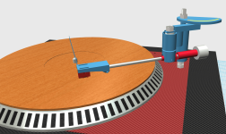
I'm glad you found my app useful. To be honest, I had no idea about the mechanical contraption you posted 10 years ago, but you know the saying, there's more than one way to skin a cat. To me as an IT guy, the digital approach was more tempting since it has two main advantages. First you don't need to build anything physical, and second the accuracy of the resulted curve is limited by the accuracy of the mechanical contraption, which for us DIY-ers working on the kitchen table corner is a real challenge. Here is my current project design. I haven't started building it yet since I'm still waiting for the all ceramic bearings. What a bad idea to order it during holidays
I'm glad you found my app useful. To be honest, I had no idea about the mechanical contraption you posted 10 years ago, but you know the saying, there's more than one way to skin a cat. To me as an IT guy, the digital approach was more tempting since it has two main advantages. First you don't need to build anything physical, and second the accuracy of the resulted curve is limited by the accuracy of the mechanical contraption, which for us DIY-ers working on the kitchen table corner is a real challenge. Here is my current project design. I haven't started building it yet since I'm still waiting for the all ceramic bearings. What a bad idea to order it during holidays
Attachments
Hi Consty,
The rendering looks very good, but to me seems that the vertical dimension it is a bit big and could generate a negative momentum. However, considering the limited space you have in the bottom of the TT, good idea to expand the TA in the upper line.
Hope ur bearing arrive regularly soonest. I may use bearing that I have in the garage while waiting my new ones that I keep just in case.
However I am not a fast guy in doing things.
Rgds
Adelmo
Hi Consty,
Sorry to bother you so much these days. I went in the Drawing. chart, changed the figure in the green cells, click on th<e Plot, but nothing change.
Instead if I click on the green cells of the data, click the green v and input n<ew data the numb<ers are recalculated but nothing change in the drawing.
May be because this file is generated with Windows and I am using Mac?
Tks n rgds
Adelmo
Hi Consty,
With my daughter PC I am able to elaborate your Chart.
Many Tks again.
Adelmo
Yes, indeed. I would have liked to keep it as flat as possible but, as you noticed too, since there wasn't enough room in the lower side, I had to be creative and go upwardsthe vertical dimension it is a bit big
. I hope this wouldn't negatively impact the TA performance. Anyway, one of the main drawbacks of this type of design is that it requires absolute spot on vertical alignment of the pivot. The slightest "Pisa tower" leaning would result in a pseudo skating force much stronger than the real skating associated to the conventional pivoted arms.I didn't check diyaudio for long time. It is so true. The arm itself doesn't generate skating force at all.Anyway, one of the main drawbacks of this type of design is that it requires absolute spot on vertical alignment of the pivot. The slightest "Pisa tower" leaning would result in a pseudo skating force much stronger than the real skating associated to the conventional pivoted arms.
Consty,
I hope you build that arm. I can't think of any reason your high control arm placement won't work. For your first attempt, I suggest you build in adjustable connecting points because the V and H alignment is so critical. There are likely to be little surprises you have to deal with and adjustable makes that easier. It won't look as pretty as the design you posted, but you'll learn more about how to build and even if it doesn't look good it can still sound good.
I also suggest mounting the tower to a separate base - not directly to the TT base. Use three screws to mount the plate with small o-rings between the bottom of the plate and the top the TT base. After the V and H is carefully set up, use the screws to dial in a tiny amount of off-vertical to deal with any skate may show up.
Doug
Consty,
My suggestion is to reduce the height of the tower as much as you can. So, the skating force caused by the unbalanced tower won't be amplified. I actually did another version of my PT arm. I tried to reduce the height of the tower as much as the design allows.
Looking at your design, I am not sure how the rear guiding mechanism works. Please note that on Frank's arm, the slot isn't a part of the guiding mechanism. It is only a protecting mechanism.
Last edited:
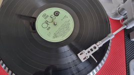
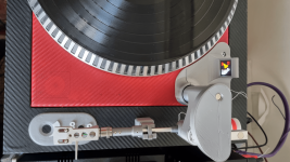
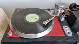
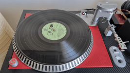
I finally did it! It took me some time but I must confess I'm very pleased with the final result. It tracks perfectly tangential, no skating, no worries.
Once again kudos to Mr. Schroeder for his genius idea!
Once again kudos to Mr. Schroeder for his genius idea!
Attachments


Hi Consty,
Looks pretty good!!
Congratulation for the build!. I am much slower than you, actually I had a small injury to 3 fingers of my left hand with a planer so I put on hold the project for few month giving priority to the recovery.. At the preset I am working to get ready a Lenco L75, a non floating TT for my LT attempt.
Shall revert in some time.
Rgds
Adelmo
Sorry to hear this. Fast recovery and good luck with your projects!I had a small injury
Hi Consty,Sorry to hear this. Fast recovery and good luck with your projects!
I have recovered 80%.
Tks
Adelmo
Hi Consty,
Planning to try to open your file with another PC.
Have a nice day, tks !
Adelmo
Sounds as good as my previous air bearing linear tracking TA I built some years ago, with the bonus that now I'm not worried about record skipping each time the tiniest grain of dust got in the way of the moving part of the air bearingAnd sounds like?
- Home
- Source & Line
- Analogue Source
- Angling for 90° - tangential pivot tonearms