There is nothing wrong with it, it provides tangential tracking. You just need to add an antiskating device.I am probably missing the point here.
But what is wrong with the approach I suggest here.
(I don’t see what’s wrong, but it is so simple there must be something wrong with it.
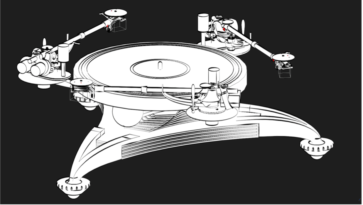
This is one of the many attempts to ensure tangential tracking using fixed centre guide links. Unfortunately the cross member pivots do not follow fixed circular paths as the stylus follows the Thales circle, which it must do for passive tangential alignment. The points attached to the tonearm describe curves named Limacons, which are associated with circles rolling on circles. I don't know how your rear pivot centres and radii are derived but they do not ensure tangential alignment at the stylus.I am probably missing the point here.
But what is wrong with the approach I suggest here.
(I don’t see what’s wrong, but it is so simple there must be something wrong with it.
View attachment 1031797
There is a movie with some lines :
and some drawings: View attachment 1031781 View attachment 1031780
The first video below illustrates a typical case of the arrangement in your diagrams. The paths of the cross member ends are shown (green and blue) to be limacons, not circles. Adjusting the parameters makes no difference.
Numerous geometries have approximated these limacons by fixed circular paths. A true tangential geometry is shown in the second video.
Regards
Bon
Following a Thales circle is only one way to construct a tangential tracking tonearm but not the only one.Unfortunately the cross member pivots do not follow fixed circular paths as the stylus follows the Thales circle, which it must do for passive tangential alignment. The points attached to the tonearm describe curves named Limacons, which are associated with circles rolling on circles. I don't know how your rear pivot centres and radii are derived but they do not ensure tangential alignment at the stylus.
According to the video the tangential alignment is achieved with at least very good approximation.
The video angle and resolution does not allow any reasonable assessment of the tangential alignment. Furthermore, the 2 diagrams explicitly illustrate the Thales circle as the basis for the tangential alignment claim.Following a Thales circle is only one way to construct a tangential tracking tonearm but not the only one.
According to the video the tangential alignment is achieved with at least very good approximation.
Hi Jim.Bon,
Your 1st video is amazing. What kind of software do you use?
Jim
I use Desmos parametric graphing. It will not be everyones cup of tea, but is remarkably accurate and flexible. You need to be comfortable with parametric expressions e.g. for straight lines (through a known point, with a known slope, joining 2 points, orthogonal to another line, etc.), circles (with known centre and radius, etc). All parameters can be entered as variable and changed at will by sliders. Graphs can be animated by varying a parameter between fixed values. It can even animate graphs varying more than one parameter simultaneously.
Just be aware that data is held on the Desmos site and is probably in the public domain. So I would not use the software for any commercially sensitive projects. It does not bother me. Mathematics and geometry should be widely shared.
Bon
it is indeed an approximation. It has been made experimentally without understanding the math to be honest.The video angle and resolution does not allow any reasonable assessment of the tangential alignment. Furthermore, the 2 diagrams explicitly illustrate the Thales circle as the basis for the tangential alignment claim.
I started out with placing circles in the playable zone of the lp.
Then I draw the tonearm with the two Pivots on both sides.
copied that one and made them tangent to the circles.
took the sides of the pivots and laid them together on a circle.
then I put a Circle on the other pivot. But a circle won’t fit on all pivots. here is the point where the limacon’s would fit (thank you Bon, I learned a whole lot from your explanation)
after that i did a check. The last three pictures are a drawing of how a build system would be .
there you can see that the between second and fourth circle the approximation is accurate enough for my cad system to not notice it. The inner and outer circle are not tangential. I think that those errors are smaller than any tolerances that I can achieve with my building skills
") .
. Suswashier,
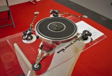
Congratulations for turning geometry into an actual tonearm. There are a couple of technical questions about it, but I think it could work. There are similar vintage arms and Jim (super10018) also has a recent design. Have you added cartridge and listened to it?
Doug
Congratulations for turning geometry into an actual tonearm. There are a couple of technical questions about it, but I think it could work. There are similar vintage arms and Jim (super10018) also has a recent design. Have you added cartridge and listened to it?
Doug
Attachments
The below is something I posted in another thread but I feel it was a distraction so I decided to post here.
-----------------------------------------------
According to the website, this product can be a game changer, particularly for parallel tracking. Unfortunately, the price is 600,000 yen ($4,600 USD). Yikes! I think those 6 figure uber turntables should just give out such a device as a freebie!
Besides the Nakamichi turntables, I'm surprised no one else thought of accessories like this. I do know a Frank Schroeder designed turntable had deliberate smaller diameter spindle at the bottom portion to allow room to shift the record for concentricity. Other than that, the so called "high end" world has not spent much time on a device like this except making bigger and heavier and brighter platters. Shouldn't turntable spindles be machined independently from the bearing shaft so they can be swapped out with different diameters and length?
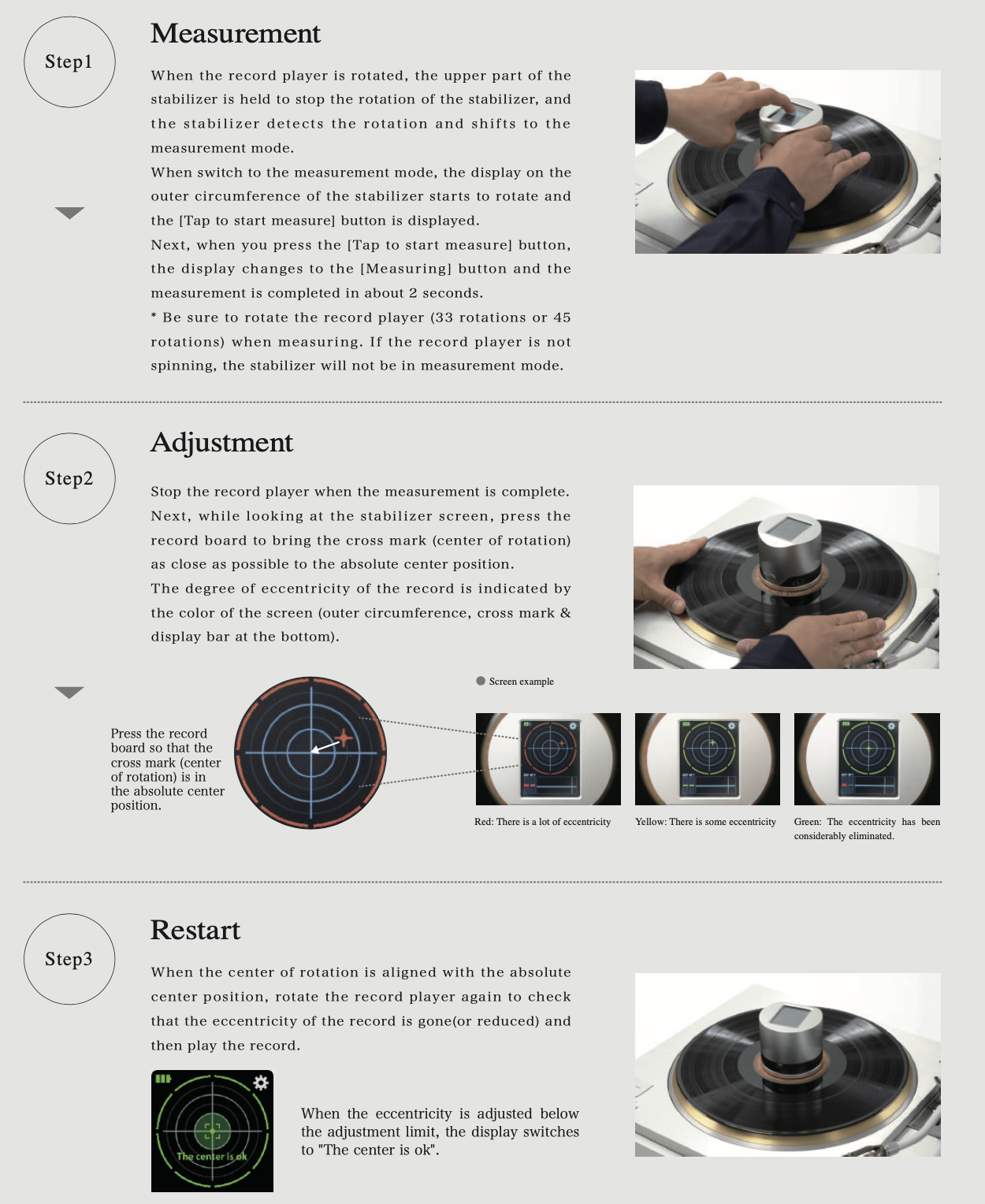

From what I read, it provides a hole enlarging tool or a reamer that allows the user to shift the record to center it based on the detection of run out grove. You physically move the disc to get concentricity. Once you dialed in, the device would tell you it's locked in dead center. Think of it as a Nakamichi turntable but manually adjusting to concentricity. Another way is to sand down the spindle to slightly smaller diameter at the bottom portion so you don't have to enlarge every record holes.
If you look closer, you can tell the hole has been slightly enlarged.

I have always wanted the turntable makers to make the spindle independent from the bearing shaft. At least the spindle should be a part of the platter instead of the bearing shaft or subplatter. Even better is to make the spindle detachable like a screw-on device to the PLATTER. Why allow bearing vibrations to be transmitted all the way up to the spindle that touches the actual record? My friend had a P-brand turntable with clamps and every time I clamp the record down to the platter, I could heard the noise from the motor. Unclamped it and the noise was gone. And the incident prompted me to dislike clamping to spindles that's machined to the subplatter and/or bearing.
Another accessory I can think of is to have two stiff platter mats to work with the detection device, one for playback on turntable and the other to get ready for the next disc. Obviously this dual mat system would require the turntable spindle to be smaller than usual if you were to do the centering away from the turntable, unless you want to enlarge every hole on your record collection.
Regardless of how one does the centering, making people and the industry to be aware of eccentricity is indeed a positive step forward. It might prompt them to come up with affordable accessories in the future. Heck, those expensive high end turntables should have an integrated system that does the centering for you!
Those detecting holes on the device.


-----------------------------------------------
According to the website, this product can be a game changer, particularly for parallel tracking. Unfortunately, the price is 600,000 yen ($4,600 USD). Yikes! I think those 6 figure uber turntables should just give out such a device as a freebie!
Besides the Nakamichi turntables, I'm surprised no one else thought of accessories like this. I do know a Frank Schroeder designed turntable had deliberate smaller diameter spindle at the bottom portion to allow room to shift the record for concentricity. Other than that, the so called "high end" world has not spent much time on a device like this except making bigger and heavier and brighter platters. Shouldn't turntable spindles be machined independently from the bearing shaft so they can be swapped out with different diameters and length?
From what I read, it provides a hole enlarging tool or a reamer that allows the user to shift the record to center it based on the detection of run out grove. You physically move the disc to get concentricity. Once you dialed in, the device would tell you it's locked in dead center. Think of it as a Nakamichi turntable but manually adjusting to concentricity. Another way is to sand down the spindle to slightly smaller diameter at the bottom portion so you don't have to enlarge every record holes.
If you look closer, you can tell the hole has been slightly enlarged.
I have always wanted the turntable makers to make the spindle independent from the bearing shaft. At least the spindle should be a part of the platter instead of the bearing shaft or subplatter. Even better is to make the spindle detachable like a screw-on device to the PLATTER. Why allow bearing vibrations to be transmitted all the way up to the spindle that touches the actual record? My friend had a P-brand turntable with clamps and every time I clamp the record down to the platter, I could heard the noise from the motor. Unclamped it and the noise was gone. And the incident prompted me to dislike clamping to spindles that's machined to the subplatter and/or bearing.
Another accessory I can think of is to have two stiff platter mats to work with the detection device, one for playback on turntable and the other to get ready for the next disc. Obviously this dual mat system would require the turntable spindle to be smaller than usual if you were to do the centering away from the turntable, unless you want to enlarge every hole on your record collection.
Regardless of how one does the centering, making people and the industry to be aware of eccentricity is indeed a positive step forward. It might prompt them to come up with affordable accessories in the future. Heck, those expensive high end turntables should have an integrated system that does the centering for you!
Those detecting holes on the device.
Let's contemplate a new device or tool that allows easy and affordable way to adjust record eccentricity. The run out groove seems like a good indicator of concentricity. First, we need to the modify the bottom portion of the the spindle to be slightly smaller that allows shifting the record. So, if we use a puck that its diameter is EXPANDABLE to match the run out groove then we can adjust accordingly? I am just spitballing here!
FX3 - asking myself - what is the advantage of rotating an usual gimbal articulation by 90°? (besides not being offtopic here....)
https://www.amazon.it/Funk-Firm-FX-3-Braccio-fissaggio/dp/B011L44D7O
This new one instead uses a rotating head shell?
c
https://www.amazon.it/Funk-Firm-FX-3-Braccio-fissaggio/dp/B011L44D7O
This new one instead uses a rotating head shell?
c
😂
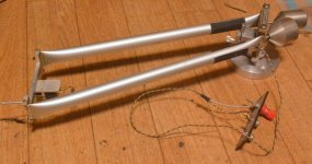
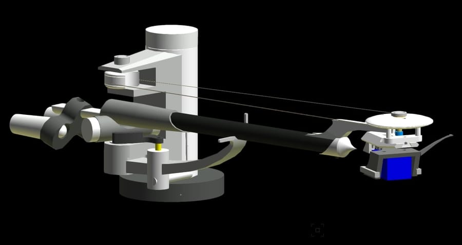
The FX3 doesn't look like it has anything special going on from the outside. The magic with this arm is due to the armtube that has an internal cross-brace (F.X) . Although it goes against my personal philosophy of keeping the armtube short this arm has come closest to matching my diy linear arm in sound quality. Close but not quite. A friend of mine owns one and it has comfortable outperformed everything we've compared it to, Graham, Townshend, Helius, SME, Origin Live.
The Raptor will most certainly use some version of the F.X armtube.
Tangential tracking is achieved using a pulley positioned above the stylus and a second at the rear of the arm, the two connected with a thread. I have no idea what type of geometry has been used.
Hopefully this arm will build on the qualities FX3, if it does Arthur will have a killer product on his hands.
I have no affiliations with The Funk Firm, though I was probably a bit gushy, when you find a product that works this well it's worth shouting about.
Niffy
Thanks for the exhaustive explanations, Niffy; in fact an internal reinforcement of the carbon tube is interesting, but on the effects on the resonances I remain of the opinion that describes them as a magic voodo: just change an ingredient's brand and the recipe changes its flavor.
Seeing that photo after that description, I had foolishly hoped that finally something new had come up in gimbal TAs: but, thinking about, using a BB for V articulation and the pin tips for the horizontal - the opposite of the usual - could be worth a try?
ciao carlo
rotating headshells do not convince me at all: but in the hands of some magician, who knows...
Niffy, thank you for alerting us to the new design in this thread!
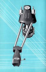
Let's be fair and put it in context here. The Funk Firm designer introduced a tangential tonearm prototype called AK1 in 2017 at an exorbitant price of $24,000. But it never materialized into an actual product. For those with good memory, it was covered in a post in this thread at the time and there's even a video of the designer explanation his creation. So it makes sense to assume the new arm is a follow up on that design. Maybe the new one is a more mature and affordable design that the designer is comfortable enough to introduce it to the public. The rotating headshell with thread genre has been covered extensively in this forum before, negative and positive. I do like it that it is out there as an option of tangential tracking.
The criticism of such design is warranted especially in having a rotating headshell right above the stylus. The concern of having the most sensitive vibration detector, the stylus, so close to a bearing is legitimate. But the irony is that one school of thought is to make the shortest arm possible that wouldn't it be possible to make the headshell the actual arm? Maybe. Here's a thought: it would be a mechanical marvel to have a rotating headshell that also allows straight VERTICAL or pistonic movement. Again, I'm just spitballing here!
2017

2022


Let's be fair and put it in context here. The Funk Firm designer introduced a tangential tonearm prototype called AK1 in 2017 at an exorbitant price of $24,000. But it never materialized into an actual product. For those with good memory, it was covered in a post in this thread at the time and there's even a video of the designer explanation his creation. So it makes sense to assume the new arm is a follow up on that design. Maybe the new one is a more mature and affordable design that the designer is comfortable enough to introduce it to the public. The rotating headshell with thread genre has been covered extensively in this forum before, negative and positive. I do like it that it is out there as an option of tangential tracking.
The criticism of such design is warranted especially in having a rotating headshell right above the stylus. The concern of having the most sensitive vibration detector, the stylus, so close to a bearing is legitimate. But the irony is that one school of thought is to make the shortest arm possible that wouldn't it be possible to make the headshell the actual arm? Maybe. Here's a thought: it would be a mechanical marvel to have a rotating headshell that also allows straight VERTICAL or pistonic movement. Again, I'm just spitballing here!
2017
2022
Last edited:
Hi all,Niffy, thank you for alerting us to the new design in this thread!
Let's be fair and put it in context here. The Funk Firm designer introduced a tangential tonearm prototype called AK1 in 2017 at an exorbitant price of $24,000. But it never materialized into an actual product. For those with good memory, it was covered in a post in this thread at the time and there's even a video of the designer explanation his creation. So it makes sense to assume the new arm is a follow up on that design. Maybe the new one is a more mature and affordable design that the designer is comfortable enough to introduce it to the public. The rotating headshell with thread genre has been covered extensively in this forum before, negative and positive. I do like it that it is out there as an option of tangential tracking.
The criticism of such design is warranted especially in having a rotating headshell right above the stylus. The concern of having the most sensitive vibration detector, the stylus, so close to a bearing is legitimate. But the irony is that one school of thought is to make the shortest arm possible that wouldn't it be possible to make the headshell the actual arm? Maybe. Here's a thought: it would be a mechanical marvel to have a rotating headshell that also allows straight VERTICAL or pistonic movement. Again, I'm just spitballing here!
2017
2022
There was a member some time ago who had a patent on that tone arm. His user name was A Wolf.
Does anyone remember him?
Sincerely,
Ralf
Andrew M. Wolff is the inventor of patent US4497053. He goes by Andy here and his username is awolff761 and his most recent posts are from 2021. I hope he's doing well.There was a member some time ago who had a patent on that tone arm. His user name was A Wolf.
Does anyone remember him?

- Home
- Source & Line
- Analogue Source
- Angling for 90° - tangential pivot tonearms