Hi Brian
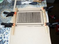
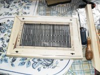
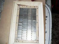
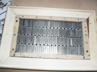
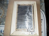
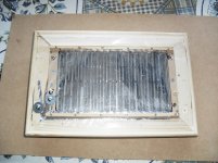
Made a frame of wood and drilled holes through the sides and put long screw's in.
Then I glue the frame to mylar.
I put a aluminum profile over the screw's and mount springs.
Attach the profile to the speaker mdf and now I can adjust the tension of the mylar.
Then I use aluminum tape 9mm wide from farnell for the conductors.
Rob
Henry, you are a maniac. In the best possible way.I marvel at all your work.
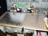
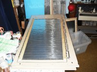
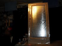
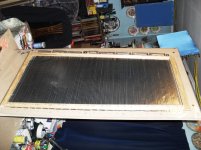
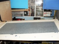
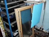
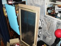
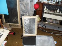
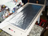
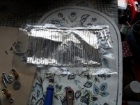
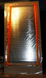
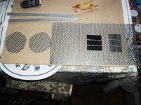
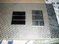
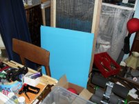
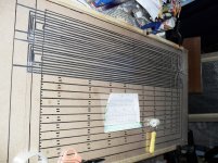
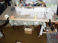
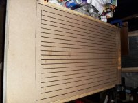
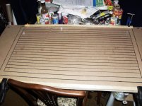
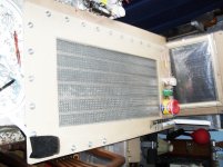
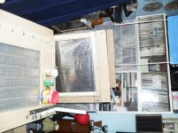
Some more for you to marvel at!! Finished latest design using 80 meters of 4.5 mm wide tape. The first 45 meters ran out before I realized. So the diaphragm is in 2 unequal parts which caused problems when wiring in parallel and the top half is louder than the bottom half. You live and learn. It is running with my first epsilon layout design (with the glued magnets) The small A4 sized design is my next rebuild.
 Then I may finish my planar headphones next.
Attachments
-
 SAM_0137.JPG857.7 KB · Views: 761
 -
 SAM_0146.JPG759.1 KB · Views: 693
 -
 SAM_0147.JPG713 KB · Views: 650
 -
 SAM_0148.JPG734.1 KB · Views: 624
 -
 SAM_0150.JPG823.8 KB · Views: 586
 -
 SAM_0151.JPG760.4 KB · Views: 124
 -
 SAM_0152.JPG716.4 KB · Views: 127
 -
 SAM_0153.JPG905.7 KB · Views: 127
 -
 SAM_0140.JPG817.3 KB · Views: 170
 -
 SAM_0139.JPG808.8 KB · Views: 147
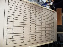
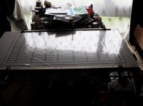
MY A4 SIZE REBUILD.
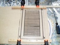
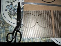
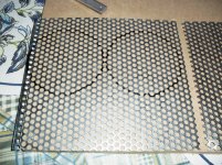
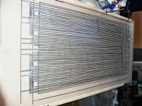
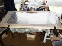
Some more photos of my latest rebuild. The last but one is the old diaphragm, and the last photo is the new tape 2.25 mm wide to fit magnets on the rebuilt diaphragm using epsilon layout. I think it's called being obsessive.!! After this it's my planar headphones, to be finished. Then it's back to the rebuilds, all that tape cutting, about 300 meters.
Some more photos of my latest rebuild. The last but one is the old diaphragm, and the last photo is the new tape 2.25 mm wide to fit magnets on the rebuilt diaphragm using epsilon layout.
I think it's called being obsessive.!! After this it's my planar headphones, to be finished. Then it's back to the rebuilds, all that tape cutting, about 300 meters.Attachments
-
 SAM_0163.JPG703.2 KB · Views: 132
 -
 SAM_0162.JPG680.5 KB · Views: 115
 -
 SAM_0160.JPG675.5 KB · Views: 103
 -
 SAM_0159.JPG779.1 KB · Views: 96
 -
 SAM_0158.JPG682.9 KB · Views: 120
 -
 SAM_0157.JPG729.6 KB · Views: 126
 -
 SAM_0155.JPG735.8 KB · Views: 146
 -
 SAM_0154.JPG777.7 KB · Views: 190
 -
 SAM_0164.JPG526.4 KB · Views: 123
 -
 SAM_0156.JPG737.6 KB · Views: 194
Last edited:
Some more photos of my latest rebuild. The last but one is the old diaphragm, and the last photo is the new tape 2.25 mm wide to fit magnets on the rebuilt diaphragm using epsilon layout.
Hi Henry
nice work!
What's the resistance of the small planars?
and, how does they sound? mine are a bit weak on bass... (size matters)
Regards
Pedro
I have stopped work on these at the moment as I ruined the diaphragm fitting it to the surround, and I have not heard it at this time. The resistance of the old diaphragm was 1.4 ohms, the new one is 4.4 ohms.Hi Henry
nice work!
What's the resistance of the small planars?
and, how does they sound? mine are a bit weak on bass... (size matters)
Regards
Pedro
Does anyone know what technique Analysis uses to solder to their aluminum conductors? In some thread I haven't yet found again there was a discussion of techniques for breaking through the aluminum oxide layer while soldering but that approach doesn't seem applicable to very thin (5.5 micron) aluminum foil.
Few
Few
Few,is this the one you were looking for?
http://www.diyaudio.com/forums/planars-exotics/197412-soldering-aluminium.html#post2725831
jer
http://www.diyaudio.com/forums/planars-exotics/197412-soldering-aluminium.html#post2725831
jer
One product that works is this:
An externally hosted image should be here but it was not working when we last tested it.
Hi Few
Just buy aluminium solder from Farnell Farnell Export
For aluminium foil it works perfect.
Rob
Just buy aluminium solder from Farnell Farnell Export
For aluminium foil it works perfect.
Rob
Thanks jer, that's the one I remembered. Unfortunately I don't think it's applicable to thin foils. I fear the mechanical scrubbing step would beat them up too much.
I'm a bit lost with the Farnell link but figured I'd make yet another attempt to find a promising source of solder for aluminum. KappAloy9 popped up but I haven't yet found a way to buy it.
Is that conventional Ersin multicore? I would have thought it would have the same problems with the oxide as other electronic solders. No?
Thanks jer, that's the one I remembered. Unfortunately I don't think it's applicable to thin foils. I fear the mechanical scrubbing step would beat them up too much.
I'm a bit lost with the Farnell link but figured I'd make yet another attempt to find a promising source of solder for aluminum. KappAloy9 popped up but I haven't yet found a way to buy it.
Is that conventional Ersin multicore? I would have thought it would have the same problems with the oxide as other electronic solders. No?
The multicore solder works like a charm on foil!
The multicore solder works like a charm on foil!
Good to know. I'll give it a try. I can't quite tell from the photo you posted which variety of Ersin solder you've had success with. My searching suggests there are multiple varieties. Does it say anything that distinguishes it on the label?
I never use solder just a penny washer, works every time and lasts for years.
I may be doing something closer to the Analysis Epsilon approach than running a single conductor over the whole diaphragm. I'd rather be able to make solder connections at the top and bottom of each conductor than rely on tons of mechanical connections.
Thanks, all.
Few
Last edited:
I haven't got it right here at the moment but at my workshop.
But from one of our companies here in Sweden You get this information...
The major important thing here is the fluss in the core that is ERSIN 362.
https://www.elfa.se/elfa3~se_sv/elfa/init.do?query=ersin#filter=0:manu|0|:89738|4|466938,;
But from one of our companies here in Sweden You get this information...
The major important thing here is the fluss in the core that is ERSIN 362.
https://www.elfa.se/elfa3~se_sv/elfa/init.do?query=ersin#filter=0:manu|0|:89738|4|466938,;
next project headphones 2 designs
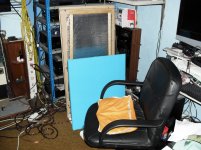
The blue ones are my latest rebuilds, 7.1 Ohms. Then headphones 2 layouts see which is the best!
The blue ones are my latest rebuilds, 7.1 Ohms. Then headphones 2 layouts see which is the best!
Attachments
some more pics of rebuilds
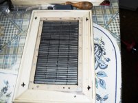
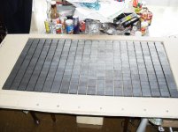
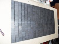
A epsilon layout design using 5 separate layouts on 1 diaphragm, using 40 x 25 x 10 mm ferrites.
A epsilon layout design using 5 separate layouts on 1 diaphragm, using 40 x 25 x 10 mm ferrites.
Attachments
-
 SAM_0205.JPG769.4 KB · Views: 109
 -
 SAM_0204.JPG726 KB · Views: 94
 -
 SAM_0203.JPG767.7 KB · Views: 97
 -
 SAM_0202.JPG752.2 KB · Views: 59
 -
 SAM_0201.JPG745.7 KB · Views: 67
 -
 SAM_0200.JPG719.2 KB · Views: 75
 -
 SAM_0198.JPG711.5 KB · Views: 83
 -
 SAM_0195.JPG690.9 KB · Views: 89
 -
 SAM_0197.JPG766.2 KB · Views: 83
 -
 SAM_0196.JPG742.8 KB · Views: 114
- Status
- This old topic is closed. If you want to reopen this topic, contact a moderator using the "Report Post" button.
- Home
- Loudspeakers
- Planars & Exotics
- analysis epsilon