Did you remove the boards? You really should’ve waited to see if the mosfet was touching the heat sink before you removed them.
And you can be as careful or not as careful as you want. All that matters is if there is continuity between heatsink and mosfet. If not, you are good. If there is, you are not. Definitely something you need to check before firing up the amp.
And you can be as careful or not as careful as you want. All that matters is if there is continuity between heatsink and mosfet. If not, you are good. If there is, you are not. Definitely something you need to check before firing up the amp.
Did you remove the boards? You really should’ve waited to see if the mosfet was touching the heat sink before you removed them.
And you can be as careful or not as careful as you want. All that matters is if there is continuity between heatsink and mosfet. If not, you are good. If there is, you are not. Definitely something you need to check before firing up the amp.
Sorry, I did NOT remove the boards.
The boards are still on the heat sinks.
So the results I posted earlier were results with mosfets in place.
You may want to try ceramic pads, P/N 4180G-ND, which I bought from Digi-Key. Easy to use.
Thanks. Just ordered them.
Right channel:
Q4 36.9 ohms
Q3 36.6 ohms
Left Channel
Q4 39.0
Q3 38.6
So all are blown.
I feel like I've not been careful enough when installing the mosfets with the pads. Appreciate any coaching before I install new ones.
I will remove the boards for inspection and photos.
So this is ohms of resistance between mosfet center pin and heatsink? If so, the mosfet is not touching the heatsink. One troubleshooting item off the list. You are good there.
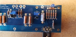
In general, burnt up r7/r8 (Source resistors) means the mosfets were pulling a lot of current. More than the source resistors could handle. And the fact that it sat idle and was not smoking until you started to play with the pots indicates some sort of overcurrent malfunction. This could be due to a lot of things
Post Mortem
Once I disconnected the amp channels I tested the PSU via dim bulb and that works.
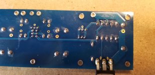
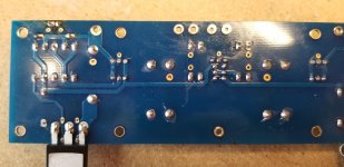
I have uploaded several photos of the right channel. Let me know if you need more views of the crime scene.
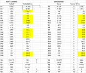
I also measured most parts on the boards and built a spreadsheet. I highlighted the ones I have questions about.
I appreciate eyes on this and suggestions:
Any thoughts on what happened? I think I got reckless turning the trimpots too fast. Things were going well. Oh well, more to learn.
I have a backup set for both amps from diyaudio. I am on the wait list for another set of boards.
Do I replace resistors et al that are damaged and try again?
Should I wipe both boards and install new parts?
As always, thanks for the help. I appreciate it.
Once I disconnected the amp channels I tested the PSU via dim bulb and that works.
I have uploaded several photos of the right channel. Let me know if you need more views of the crime scene.
I also measured most parts on the boards and built a spreadsheet. I highlighted the ones I have questions about.
I appreciate eyes on this and suggestions:
Any thoughts on what happened? I think I got reckless turning the trimpots too fast. Things were going well. Oh well, more to learn.
I have a backup set for both amps from diyaudio. I am on the wait list for another set of boards.
Do I replace resistors et al that are damaged and try again?
Should I wipe both boards and install new parts?
As always, thanks for the help. I appreciate it.
Attachments
Once I disconnected the amp channels I tested the PSU via dim bulb and that works.
I have uploaded several photos of the right channel. Let me know if you need more views of the crime scene.
I also measured most parts on the boards and built a spreadsheet. I highlighted the ones I have questions about.
I appreciate eyes on this and suggestions:
Any thoughts on what happened? I think I got reckless turning the trimpots too fast. Things were going well. Oh well, more to learn.
I have a backup set for both amps from diyaudio. I am on the wait list for another set of boards.
Do I replace resistors et al that are damaged and try again?
Should I wipe both boards and install new parts?
As always, thanks for the help. I appreciate it.
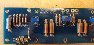
Can we get a wider pic of the mosfets so we can make sure they are installed in the correct location? Can you verify jfets are and ztx devices in the current limiting circuit are in correct locations?
R3 likely got toasted when things went bad and you got large DC offset.
A fairly large amount of current can flow through R3 and R4 at high output
levels, so I personally use 2W resistors there.
Dennis, Thanks for this advice. I will switch to 2W. Are there any other changes you have made in your resistors?
- Home
- Amplifiers
- Pass Labs
- An illustrated guide to building an F5