First “bigger” build being contemplated.
So I got my feet wet with building an ACA a couple of months ago. Now that it’s cold outside, I am thinking of building a F5. Before I start asking my questions, I’ll give a little background of the ins/outs.
I currently have the ACA taking input from Raspberry Pi Moode Audio setup and an Allo Piano DAC. The ACA was the standard kit purchased here this last summer. Outs are to a couple of Overnight Sensations on my desk. The low end is going thru a basic class D to a Paul Carmody Voxel sub. All in all, I am pretty pleased with this sound, but I’ve got the amp building bug.
I also have my laptop running through a cheap USB DAC to an old Yamaha AVR to a pair of Maggie 0.7’s. An old Yamaha sub handles the low end. I guess the end goal is to replace the Yamaha AVR going to the Maggies.
So back to feeding the amp building bug...here are the questions:
Greg
So I got my feet wet with building an ACA a couple of months ago. Now that it’s cold outside, I am thinking of building a F5. Before I start asking my questions, I’ll give a little background of the ins/outs.
I currently have the ACA taking input from Raspberry Pi Moode Audio setup and an Allo Piano DAC. The ACA was the standard kit purchased here this last summer. Outs are to a couple of Overnight Sensations on my desk. The low end is going thru a basic class D to a Paul Carmody Voxel sub. All in all, I am pretty pleased with this sound, but I’ve got the amp building bug.
I also have my laptop running through a cheap USB DAC to an old Yamaha AVR to a pair of Maggie 0.7’s. An old Yamaha sub handles the low end. I guess the end goal is to replace the Yamaha AVR going to the Maggies.
So back to feeding the amp building bug...here are the questions:
- Was thinking of starting with the Universal Power Supply PCB, also from the store here. Is that a good starting point?
- Should I plan on building it to support the F5 Turbo, and if so, where do I find specifics of how to upgrade the UPS to support the F5 Turbo? Am I correct in thinking the transformer and output caps are the major changes needed?
- Which F5t do I build for, V1, V2, or V3?
Greg
As a f5t owner, first question I would ask is “how loud do you listen with the Maggie’s”?
F5t is a great amp. But even though it’s the big brother of the f5 and “turbo” it will show it’s weaknesses into a low ohm, low sensivity speaker like that if you like it loud.
I’ve seen3.6 Maggie’s peg the meters on a big solid state Mac amp. And it wasn’t all that loud.
And you will likely want/need a preamp. Main differences of f5 turbo vs f5 is an additional pair of output mosfets, higher voltage rails (this is optional), bigger psu (more capacitance, bigger transformer) and most important...more heatsinks.
Greg -
Yes, PSU is as good a place to start as any.
You can't really make an F5 into a F5T, you essentially need to choose one and build it.
As for which to build, the differences are basically thus; V1 is a slightly hot rodded standard F5, V2 is a 5U 400mm deluxe chassis, V3 is two 5U 400mm deluxe chassis running as monoblocks.
As for advice and direction, we live about a half hour from each other. I'm always happy to help! Drop me a PM.")
Yes, PSU is as good a place to start as any.
You can't really make an F5 into a F5T, you essentially need to choose one and build it.
As for which to build, the differences are basically thus; V1 is a slightly hot rodded standard F5, V2 is a 5U 400mm deluxe chassis, V3 is two 5U 400mm deluxe chassis running as monoblocks.
As for advice and direction, we live about a half hour from each other. I'm always happy to help! Drop me a PM.
HatlessChimp - Here's a good part that's currently available;
KBPC3502T GeneSiC Semiconductor | Mouser
KBPC3502T GeneSiC Semiconductor | Mouser
So it's like a Non Return Valve in plumbing. Current can only go one way through.
In a way.
A diode is like a non-return valve. This is an arrangement of 4 diodes that convert AC to DC.
In your analogy, simplistically it would change the motion of ocean waves (alternating) to the motion of water coming out of your taps (direct flow).
Cheers. I know nothing about them. Just seen a few people had them. So do they go between the transformer and the dit psu board? Do I only need one?HatlessChimp - Here's a good part that's currently available;
KBPC3502T GeneSiC Semiconductor | Mouser
I'm learning all this stuff on the fly whilst I try and build projects. Hopefully in 5 years time I'm up to date with electronics and not just a assemble by numbers guy.
I had a quick read up the other night. It appears like they stop current running backwards into the transformer. Is that correct?
Cool. So would one have this after the transformer then into a bank of capacitors? Sorry if I sound stupid, cos I am lol. Still getting my head around it all and I appreciate the time taken to reply back to me.In a way.
A diode is like a non-return valve. This is an arrangement of 4 diodes that convert AC to DC.
In your analogy, simplistically it would change the motion of ocean waves (alternating) to the motion of water coming out of your taps (direct flow).
That's right.
So the transformer takes the 230/110v sine wave from your wall and changes it into whatever voltage.
The rectifier then takes the sine wave and turns it into DC.
The capacitors then act as short term reservoirs that then smooth the residual 'waviness' of the DC to make it nice and smooth. It also provides a store of energy for when a transient demand takes place.
General order is:
WALL=Fuse=Switch=Transformer=Rectifier=Caps=AMP
So do I need a diode bridge if I'm running a DIY Audio Universal PSU?That's right.
So the transformer takes the 230/110v sine wave from your wall and changes it into whatever voltage.
The rectifier then takes the sine wave and turns it into DC.
The capacitors then act as short term reservoirs that then smooth the residual 'waviness' of the DC to make it nice and smooth. It also provides a store of energy for when a transient demand takes place.
General order is:
WALL=Fuse=Switch=Transformer=Rectifier=Caps=AMP
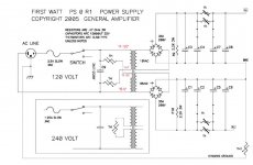
No, that board looks like it has onboard diodes to carry out rectification.
I think this is the one you refer to:
diyAudio Power Supply Circuit Board v3 illustrated build guide
I think this is the one you refer to:
diyAudio Power Supply Circuit Board v3 illustrated build guide
Yeah that's it. Cool. So what's the deal with the CRC. Cap, Resistor,Cap...etc.No, that board looks like it has onboard diodes to carry out rectification.
I think this is the one you refer to:
diyAudio Power Supply Circuit Board v3 illustrated build guide
I like the look of the big screw terminal caps, I'm sure they are not cheap. I'd like to make an amp one day with them, if just for looks haha.
Surely there is some good books out there regarding Diy Amp design.
The CRC is a filter section to further improve the smoothness of the DC and the stability under load. There is some good info here about all aspects of the power supply:
Power Supplies, Filter Circuits
There is a good list of books here:
Amplifier Design Book
Also look for Bob Cordell's book.
It helps to have a basic grasp of electronics before delving too deep into some of those books, but still worthwhile reading them if you really want to learn.
Power Supplies, Filter Circuits
There is a good list of books here:
Amplifier Design Book
Also look for Bob Cordell's book.
It helps to have a basic grasp of electronics before delving too deep into some of those books, but still worthwhile reading them if you really want to learn.
Thanks for all the info!The CRC is a filter section to further improve the smoothness of the DC and the stability under load. There is some good info here about all aspects of the power supply:
Power Supplies, Filter Circuits
There is a good list of books here:
Amplifier Design Book
Also look for Bob Cordell's book.
It helps to have a basic grasp of electronics before delving too deep into some of those books, but still worthwhile reading them if you really want to learn.
As a f5t owner, first question I would ask is “how loud do you listen with the Maggie’s”?
F5t is a great amp. But even though it’s the big brother of the f5 and “turbo” it will show it’s weaknesses into a low ohm, low sensivity speaker like that if you like it loud.
I’ve seen3.6 Maggie’s peg the meters on a big solid state Mac amp. And it wasn’t all that loud.
And you will likely want/need a preamp. Main differences of f5 turbo vs f5 is an additional pair of output mosfets, higher voltage rails (this is optional), bigger psu (more capacitance, bigger transformer) and most important...more heatsinks.
Great comments. Thx. I don’t listen to the Maggie’s very loud, but I do appreciate their clarity. I know being low ohm and inefficient may cause issues with any amp trying to drive them. My listening space is fairly small. I am thinking the F5t v2 may get me what I want, but the build is what I am interested in. Maybe I will, much to my wife’s dismay, decide on a more efficient speaker build after the amp. A proper preamp build, or purchase, is definitely an option I have considered as well.
I am keenly interested on what transformers and capacitors to consider to up the voltage rails on the PSU. I am also aware that I will need to go with a 5U 400 mm chassis for greater heat dissipation. Since 6L6 is so close geographically, which I didn’t previously notice, I am going to try connecting to get some first hand advice.
As always, I SO appreciate the kind help you guys always provide to the beginners on this forum.
Greg
- Home
- Amplifiers
- Pass Labs
- An illustrated guide to building an F5