However I note that he found the gain to be only just adequate. I also note that when he went from the 47PP to the Tabor, he increased the +B to about 500V and went back to using a 100K P2P resistor with a higher current through the 6AU6. He obviously needed that extra gain which the higher P2P resistor gave him. The benefit he seemed to be describing was in higher gm which made the circuit work better. If you can achieve higher gm without reducing P2P then thats got to be the best possible result.
I have just found the tabor schematic and it turns out that he used a 68K P2P resistor and used the extra voltage to generate extra current through the 6AU6.
My mistake.
Shoog
In your own defence, you may have remembered an earlier version of the Tabor schematic. I believe he changed to the smaller P2P resistors after the discussion took place here (linked previously.)
The key parameters for the input tube (as I see it) are high plate resistance and high transconductance at the operating point. The high Rp helps the output stage work better and the high Gm gives you more current swing which the output stage converts to volts.
Many high Gm tubes are usually no higher than a typical general purpose pentode at very low operating currents. This is why the 6AU6 takes some beating. I had a rough time finding better candidates. An EF80 comes to mind as being marginally better. Also a 6AC7 but it's metal only. Some of the comprehensive data sheets will have a transconductance vs plate current graph at different screen voltages - very helpful!
You should perhaps take what I have to say with a grain of salt. I can't claim any experience other than thinking about the amp a great deal. I never got around to building it. I'm interested to hear of your progress.
I've just gone back and reread the tubecad article, and unfortunately it makes it clear that all of the conflicting design principles make it a hell of a juggling act to get it all to work.
I have a few things in my favour in my favour;
-I intend to use capacitance coupling which simplifies tying the two stages together no end.
-I have voltage to burn.
-The 807 has extremely low plate to grid capacitance so I can go high with the P2P resistor if I keep the current through the 6AU6 at least at 5mA.
I am thinking of CCS loading the 6AU6's rather than dropping the P2P to feed the 6AU6's. I will burn some voltage in the tail of the LTP. I can well understand the benefits of a low P2P resistor, and I'm finding it a little difficult to put my finger on why this isn't going to be the better option in the end.
Still theres a lot that needs hard thinking about. All interjections help to clarify my thoughts so keep them coming.
Shoog
hey-Hey!!!,
The g2 current in the LTP circuit is why I build a cascode to develope the flat plate curves. These are flattest with triode/MOSFET constructions. It is the flat curve/high impedance that provides the most FB. Lower the plate Z and FB level decreases.
In my circuit, I am currently running 560V of B+ with 15k plate loads and 16 mA per leg. The Ec2 of the cascode is 110V. Lower element is a 6H6P and the upper is the now-discontinued FQP1N60 Fairchild MOSFET. The 30% taps are feeding the plate loads.
cheers,
Douglas
I'm now thinking of running the 6AU6 at 10mA with a 68K plate load. Seems that the transconductance is the most important element of the driver design and you have to get the plate current up to get the max transconductance. Running it in this configuration with a high P2P would give excessive gain and probably distort the P2P resistor.
It seems that Alex Kitic might just have know what he was doing when he chose the ECC81 for a driver !!
Shoog
It seems that Alex Kitic might just have know what he was doing when he chose the ECC81 for a driver !!
Shoog
Gary had similar thoughts about getting the current up in the driver stage. He was considering using an interstage transformer(!) to free the driver operating current from the current through the P2P resistor. Don't know if he ever tried it though as he was on to something else.
RCA in mid 1950's did market a high quality 50W amp, using such a plate to plate and also plate to cathode feedback. Presently can't pin the source.
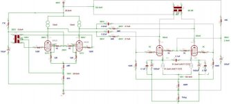
Seems to me that the 68K neg feedback loops from o/p stage anodes to driver will reduce the input Z to each o/p stage and will additionally load 6AU6 stage to distort at high signal levels. The 807's will require considerable driving voltage. What output power are you expecting ?
This makes the 0.22uF coupling caps look very small. A 1uF would be more in line. It will be interesting to do the CAD analysis.
The currrent source in each driver anode load appears to work out equivalent roughly 20K load in each half. I wouldn't be suprised if you might have to double the driver current to keep stage distortion under wraps.
richj
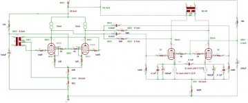
A slight correction to the schematic to convay what I wanted.
Point noted.
The spec sheet on the 807 says to expect 38watts at this operating point.
The dificulty with the loading of the 6AU6 is that if the P2P resistor is increased it creates additional drive voltage which is likely to overload the stage. The final output voltage is dictated by the drive current and not voltage. The idea is to keep the drive voltage down whilst generating plenty of drive current. Potentially this stage can generate +/- 6mA of drive current which should keep up output voltage. Also in this arrangement the P2P resistor, in combination with the 807 gain and miller capacitance, dictates the high frequency response. Going high with the load kills the top end.
Gary Pimm had good results with a 68K P2P resistor with only about 5mA current through each 6AU6. My decision is mostly copycating Gary's success, but I want to push 10mA.
How did you arrive at this figure, please.
I have to admit this whole project is on the edge of my comprehension and something of a learning experience.
Shoog
his makes the 0.22uF coupling caps look very small. A 1uF would be more in line.
Point noted.
Seems to me that the 68K neg feedback loops from o/p stage anodes to driver will reduce the input Z to each o/p stage and will additionally load 6AU6 stage to distort at high signal levels. The 807's will require considerable driving voltage. What output power are you expecting ?
The spec sheet on the 807 says to expect 38watts at this operating point.
The dificulty with the loading of the 6AU6 is that if the P2P resistor is increased it creates additional drive voltage which is likely to overload the stage. The final output voltage is dictated by the drive current and not voltage. The idea is to keep the drive voltage down whilst generating plenty of drive current. Potentially this stage can generate +/- 6mA of drive current which should keep up output voltage. Also in this arrangement the P2P resistor, in combination with the 807 gain and miller capacitance, dictates the high frequency response. Going high with the load kills the top end.
Gary Pimm had good results with a 68K P2P resistor with only about 5mA current through each 6AU6. My decision is mostly copycating Gary's success, but I want to push 10mA.
The currrent source in each driver anode load appears to work out equivalent roughly 20K load in each half.
How did you arrive at this figure, please.
I have to admit this whole project is on the edge of my comprehension and something of a learning experience.
Shoog
Attachments
richwalters said:...
Seems to me that the 68K neg feedback loops from o/p stage anodes to driver will reduce the input Z to each o/p stage and will additionally load 6AU6 stage to distort at high signal levels.
Of course, and the need of the CCS on the plate is questionable.
richwalters said:..
This makes the 0.22uF coupling caps look very small.
Only if the feedback resistor is connected after the condenser.
Regards Andreas
Andreas....I missed part of the schematic lines...bit thin on my matt screen.
My comments on increasing the 6AU6 operating current is not ideal as tubes will be running close to plate dissipation levels. I wouldn't like to push these tubes any more.
I presume (shoog) you are using a solid state CCS used in the LTP driver stage. No-one has mentioned that it could alter the sound quality. I find it does. Anyone share this opinion ?
richj
I presume (shoog) you are using a solid state CCS used in the LTP driver stage. No-one has mentioned that it could alter the sound quality. I find it does. Anyone share this opinion ?
Indeed it will be a SS. I can live with that even if no-one else can. I have had good results with SS anode loads.
Of course, and the need of the CCS on the plate is questionable.
Its only possible to get about 4-5mA of current through the 6AU6 with the voltage available and no CCS. This is the limiting factor of the 6AU6, in this application, rather than its voltage generating abilities.
The CCS takes a considerable load off the P2P resistor which is a potential source of distortion.
If I increase the grid leak resistor of the 807 to 500K it will presumably improve the loading on the 6AU6.
Shoog
Increasing the grid leaks on the 807's to 500K isn't the done thing.
For commerical LTP apps using EF184 LTP, take a brouse at the Radford STA100 schematic at
http://www.freeinfosociety.com/electronics/schemview.php?id=2364.
This site has alot of schematics and using EF184 is a step upwards than 6AU6's.
Although quite popular in the late 1960's this amp used a massive amount of global nfb, claimed unconditionally stable in anyload even no load.
Many MI players at the time (even myself) never liked the sound of this amp even though it could make alot of noise and mainly used as areinforcing amp, I wouldn't recommend running todays KT88's at 60mA at 600V B+. The design of the power supply could do with another improvement.
richj
There is also the RCA 6L6 example using inverse feedback. This could save one alot of time.
http://www.freeinfosociety.com/electronics/schemview.php?id=2393
richj
http://www.freeinfosociety.com/electronics/schemview.php?id=2393
richj
Increasing the grid leaks on the 807's to 500K isn't the done thing.
According to the datasheet, for 807 in pure class A operation, it is acceptable to increase this to 500K. The 807 draws very little grid current.
For commerical LTP apps using EF184 LTP,
The EF184 has slightly more headroom and has better current swing - but it has a lower ra which is one of the critical attributes of a driver in a Partial feedback amplifier. It seems to be a bit more linear than the 6AU6, though I would guess that the LTP configuration would correct the 6AU6 somewhat.
Shoog
Norman Crowhurst did articles on the very subject...worth a brouse...www.audioxpress.com/resource/audioclass
part 5.
Why did you choose 807's and not the 6L6/5881 family ? Keeping with Intoctal sockets permits using a vast group of tubes.
The highest value of grid bias resistance may be fine for NOS but I learn't my lesson using 6550 series which require a magnitude lower value.
richj
part 5.
Why did you choose 807's and not the 6L6/5881 family ? Keeping with Intoctal sockets permits using a vast group of tubes.
The highest value of grid bias resistance may be fine for NOS but I learn't my lesson using 6550 series which require a magnitude lower value.
richj
I have a rake of 807 from when I built the RH807 (another SE amp based on the same principles). A good cheap valve overall.
I'm not entirely happy with the result of my design so far. I think the CCS loads is a good idea, but potentially very tricky to set up well. Since final gain is generated by the driver current swing I like the idea of +/-5mA current swing (or more), but the elegance of using the P2P resistor for driver current is very appealing.
Also the 807 will distort very badly when the linear relationship between plate and screen current brakes down (it goes from about 1mA to 10mA very quickly). Not really a problem as I can't see me driving it that hard, still not aesthetically satisfying.
I don't think I need a regulated screen supply for the 6AU6, but I think it would be wise to have one for the 807's.
I think i'm going to sit on it for a week or so to see if any inspiration occurs.
Shoog
Yes... it isn't easy coming to a conclusion with a particular design. One always finds better..I wanted a non flightly design which had repeatable stability with same type tubes from different vendors without all the hassle of balance adjustments. It's nice to be able to slot in NOS,CVC,Svet and so on without setup hassle and tinker. With some pentode signal tubes this isn't possible without screen adjustment for min thd.. I ended up contented using a simple Williamson type driver and concertina front end and thd was just as low.
So I'm one of those who regulary use pentodes as triodes and for simple screening connect anode to ground and use screen grid as anode..
As to regulated screen supplies using pentode LTP, some early designs used it, some not. The Radford STA25R did and STA100 didn't. The STA100 also used pair EF184 LTP but the thd was so high that more than 30dB global nfb was used to get it down. Perhaps it was this that made it musically poor.
http://www.freeinfosociety.com/electronics/schemview.php?id=2363
The thing to watchout using a LowZ screen supply for the 807's, make sure it can not to exceed max g2 ratings. Is sure way to ruin good tubes. Regulation is desirable for min thd.
richj
Hi,
The discussion re the 6au6 tube prompted me to recall a paper entitled "Which tube shall I use" - George Fletcher Cooper. Google provides an address to a 9 page pdf file in which the 6au6 is found not superior to the 6ba6.....it certainly surprised me!! Then again, I have two radiogram chassis with pp 6v6 output stages which use 2 x 6ba6 in the driver stages. Someone did their homework!!
I am impressed with the later pages of the paper where Vg1 is plotted against transconductance figure derived from the effect of un-bypassed Rk and the influence upon d3 levels........
Regards,
Graeme
- Status
- This old topic is closed. If you want to reopen this topic, contact a moderator using the "Report Post" button.
- Home
- Amplifiers
- Tubes / Valves
- An idea for a partial feedback pentode amp using 6AU6's and 807's