Having reread Gary Pimm's excellent article I will try to supply the current through the P2P feedback resistor as it seems that he got a real step change with that mod. I was planning on the usual 100K, but if I drop that to 60K then it should make the mod easier to implement. I will then probably have to run the 807's at a higher voltage - say 350V.
It would be nice to go DC coupled, but I really want a simple power supply and the two things don't seem to mix.
Shoog
It would be nice to go DC coupled, but I really want a simple power supply and the two things don't seem to mix.
Shoog
hey-Hey!!!,
I'd get rid of the 150R in the cathode node of the 6AU6. You'll also be able to do away with the two g2 bypass caps. Use also a single dropping resistor.
If you aren't stuck on the 6AU6, consider the EF184.
What are you planning for the output? I have heard a few nice 807 amps running 10k a-a, with 40% U-L taps. That anode load also allows a fairly high B+ without excaping Class A.
cheers,
Douglas
hey-Hey!!!,
One more thing, I doubt you'll need all the plate FB. 20-30% has worked well for me, and I have always found the full dose excessive. Get an output with a few taps. 20, 40, and 60% perhaps? 25, 37.5, and 50% perhaps? My Peerless clones from Heyboer get done at 20, 30 and 40%.
cheers,
Douglas
One more thing, I doubt you'll need all the plate FB. 20-30% has worked well for me, and I have always found the full dose excessive. Get an output with a few taps. 20, 40, and 60% perhaps? 25, 37.5, and 50% perhaps? My Peerless clones from Heyboer get done at 20, 30 and 40%.
cheers,
Douglas
'd get rid of the 150R in the cathode node of the 6AU6. You'll also be able to do away with the two g2 bypass caps. Use also a single dropping resistor.
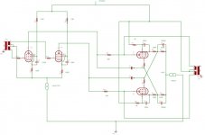
The 150R are normal cathode bias setting resistors. You will notice that the grids are referenced to the top of the CCS. This was chosen to avoid the need for a negative supply for the CCS.
What advantage will dropping the g2 bypass bring.
One more thing, I doubt you'll need all the plate FB. 20-30% has worked well for me, and I have always found the full dose excessive. Get an output with a few taps. 20, 40, and 60% perhaps? 25, 37.5, and 50% perhaps? My Peerless clones from Heyboer get done at 20, 30 and 40%.
The P2P feedback resistor is chosen to eliminate a seperate anode load resistor. It might be possible to bring it up to 68K, but it defined by the 5mA current through the 6AU6.
Shoog
Shoog said:...
The P2P feedback resistor is chosen to eliminate a seperate anode load resistor. It might be possible to bring it up to 68K, but it defined by the 5mA current through the 6AU6.
Shoog
Hi Shoog,
you need a high load resistor for high amplification of the first stage (the 68K load/feedback resistor is seen smaller than it is by the amplification factor of the 807).
Regards Andreas
If you haven't already, it might be helpful to read John Broskie's article on partial feedback amps on TubeCad Journal:
http://www.tubecad.com/march2001/2001_03.pdf
Looking at the output stage as an I-V converter helped me to understand how the circuit worked. Never actually built the thing though.
http://www.tubecad.com/march2001/2001_03.pdf
Looking at the output stage as an I-V converter helped me to understand how the circuit worked. Never actually built the thing though.
And there's an exchange here, too where Gary P talks about how different this is from typical amps in relation to operating points:
http://www.diyaudio.com/forums/showthread/t-49395-p-2.html
http://www.diyaudio.com/forums/showthread/t-49395-p-2.html
I have read the tubcad article and have a fair understanding of it. I understand that the anode load wants to be higher, but without a massively higher +B its a compromise. Having a normal resistor anode load places it in parallel with the P2P resistor. Eliminating the anode load brings sonic benefits (according to Gary P), but at the cost of a lower anode load and hence lower gain. Since I need plenty of gain this could be a real problem. Maybe a CCS load in parallel with a higher P2P resistor would be the best compromise.
Shoog
Shoog
Shoog said:...Maybe a CCS load in parallel with a higher P2P resistor would be the best compromise.
Shoog
The P2P resistor is shunting the CCS, better take a feedback path to the cathods of the driver.
Regards Andreas
The P2P resistor is shunting the CCS, better take a feedback path to the cathods of the driver.
Different type of feedback - different kind of amp.
Shoog
Shoog said:
Different type of feedback - different kind of amp.
Shoog
Yes.
The feedback from P2P decreases the input impedance of the 807 and increases the distorsions of the driver (mostly 2nd order).
The feedback from the plate of the output tube to the cathod of the driver tube includes all tubes.
Andreas
And there's an exchange here, too where Gary P talks about how different this is from typical amps in relation to operating points:
http://www.diyaudio.com/forums/show...-49395-p-2.html
Excellent reference. I even contributed a little myself. It makes things a lot clearer.
Seems as though I won't be getting the gain I had hoped for with such a low P2P resistor. Its a headache inducing balancing act to get everything to play to the same tune. If I do introduce anode CCS loads onto the 6AU6's then I will have to dynamically set the screen voltage to get the thing stable.
Certainly it looks like the input transformer will have to be dropped/revised.
Shoog
If the 6AU6 was enough to drive the 1624's in the Tabor amp, it should drive 807s.
It's been a while since I looked at this, but I understood the first stage as being important to get current swing, not voltage swing. A smaller P2P helps this happen by letting more operating current get to the 6AU6 where it runs at higher transconductance. Yes, the voltage swing drops out of the 6AU6, but the output stage reacts to changes in input current.
It's been a while since I looked at this, but I understood the first stage as being important to get current swing, not voltage swing. A smaller P2P helps this happen by letting more operating current get to the 6AU6 where it runs at higher transconductance. Yes, the voltage swing drops out of the 6AU6, but the output stage reacts to changes in input current.
I agree to a certain extent. However it is only partial feedback and the 6AU6 is still required to do all of the voltage amplification. If the anode load is so low it will kill the amplification. Its a very delicate balancing act to get current drive to balance amplification.
Shoog
Shoog
hey-Hey!!!,
If you're biasing the 6AU6 with the 150R resistors, the CCS isn't going to do anything useful. I also mis-wrote on the elimination of the g2 bypass. You'd use a single dropping R and bypass C, instead of the duals. Again, with gain an issue, there are many good pentodes to look at. EL84, 6CL6, 12HL7, 12BY7, 6EJ7/EF184, 7788, E55L....and then there's the cascodes: 6C4C, 5687, ECC99, 6H30, 6H6P or put a MOSFET on top and use just a single pair of well matched triodes. The triode/MOSFET offers a *VERY* high output Z( effective plate resistance of the faux pentode ).
Take your plate voltage signal from part way along the anode coil. You hook the front end up to the respective tap( usually the UL tap ) from the final's grid it's driving. When getting custom Iron made, it is up in the air where you get the taps put. End of layer puts some restriction on this location...With the 20-layer primary of the S-265-Q, it is 10% increments, with the 16-layer S-271-S you get 12.5% increments all the way out to the plate.... Get a variety to experiment with, you will probably find them as useful as I have.
cheers,
Douglas
If you're biasing the 6AU6 with the 150R resistors, the CCS isn't going to do anything useful. I also mis-wrote on the elimination of the g2 bypass. You'd use a single dropping R and bypass C, instead of the duals. Again, with gain an issue, there are many good pentodes to look at. EL84, 6CL6, 12HL7, 12BY7, 6EJ7/EF184, 7788, E55L....and then there's the cascodes: 6C4C, 5687, ECC99, 6H30, 6H6P or put a MOSFET on top and use just a single pair of well matched triodes. The triode/MOSFET offers a *VERY* high output Z( effective plate resistance of the faux pentode ).
Take your plate voltage signal from part way along the anode coil. You hook the front end up to the respective tap( usually the UL tap ) from the final's grid it's driving. When getting custom Iron made, it is up in the air where you get the taps put. End of layer puts some restriction on this location...With the 20-layer primary of the S-265-Q, it is 10% increments, with the 16-layer S-271-S you get 12.5% increments all the way out to the plate....
Get a variety to experiment with, you will probably find them as useful as I have.cheers,
Douglas
Shoog said:I agree to a certain extent. However it is only partial feedback and the 6AU6 is still required to do all of the voltage amplification.
I think you should try it. I have a private email from Gary that occurred around the time of the thread I linked previously where he said he went to smaller P2P resistors (from over 100K to 68K) and found everything worked better.
I think you should try it. I have a private email from Gary that occurred around the time of the thread I linked previously where he said he went to smaller P2P resistors (from over 100K to 68K) and found everything worked better.
That useful and interesting.
However I note that he found the gain to be only just adequate. I also note that when he went from the 47PP to the Tabor, he increased the +B to about 500V and went back to using a 100K P2P resistor with a higher current through the 6AU6. He obviously needed that extra gain which the higher P2P resistor gave him. The benefit he seemed to be describing was in higher gm which made the circuit work better. If you can achieve higher gm without reducing P2P then thats got to be the best possible result.
Its such a complex balancing act that its difficult to know exactly what decisions he made over time - and unfortunately he's not here to tell us.
I think the bottom line would be to achieve the max +B to allow the biggest P2P resistor without sacrificing driver current.
If you're biasing the 6AU6 with the 150R resistors, the CCS isn't going to do anything useful. I also mis-wrote on the elimination of the g2 bypass. You'd use a single dropping R and bypass C, instead of the duals
I can buy into the single cap and resistor for the screens, but if using just the 150R referenced to earth surely there is no longer any differential aspect to the LTP. Why is it so bad to have those 150R in there. I would have though a bit of degenerative feedback would have balanced DC and helped things along sound wise.
Shoog
Just as a though experiment:
I have four 6AQ5's lying around. This has a mu of about 60 so in pentode mode with a high anode load I could expect to get gain of about 30-40. This is an ouput pentode so achieving 5mA of anode current at relatively low voltage should be a breeze. Of course the downside would be that the Ra has dropped right off to about 50K from the 6AU6's 1meg.
Thought/comments ??
Shoog
- Status
- This old topic is closed. If you want to reopen this topic, contact a moderator using the "Report Post" button.
- Home
- Amplifiers
- Tubes / Valves
- An idea for a partial feedback pentode amp using 6AU6's and 807's