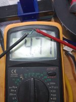
I haven’t seen wrong color code on resistor in my whole life. That one is color coded as 4.7 MΩ.
If green LED glows, then resistor value is OK.
If testing regulator on the bench, direct supplied from some lab power supply, add small capacitors at regulator input and output (220-470 uF).
If green LED glows, then resistor value is OK.
If testing regulator on the bench, direct supplied from some lab power supply, add small capacitors at regulator input and output (220-470 uF).
Variac + testing regulators attached to power supply board is perfectly OK. Other method is to supply PS board rectifiers from adjustable lab supply, for those that don’t have variac at their disposal.
In case that bare R21 module is being tested, some capacitance must be attached to input and output.
In case that bare R21 module is being tested, some capacitance must be attached to input and output.
I found the cause of the strange behaviour of my R21, a faulty multiturn potentiometer.... Now I have tested three plus and one minus R21 with a lab supply of 13,8 volt output. Regulation of output voltage is fine. Next step using two + versions for my F1. Thanks for the support and I will report back on the sound

That was hard to find for sure. Explains why there was no visible mistake to spot on pictures.
When assembling PS, take care to put regulator close to output terminals, with reference ground wire short as possible and connected to ground point at the very PS output. R21 output should be connected, again with short wire, to the PS output. Input wire can be as long as it is required to connect after first reservoir capacitor.
Looking forward to hear your impressions with F1.
When I ordered the PCBs, I forgot to include the labeling on the bottom side of the PCBs:-( Therefore, I am not quite sure about the orientation of the OpAmp and the optocoupler on the positive regulator (the build guide shows only the bottom of the negative regulator).
My guess: Placing both PCBs side by side (a mirror plane in between), for the posivitve regulator the OPA828 is turned by 180° (bar on the right side), the optocoupler has its point still on the left bottom side. Correct? (And many thanks for providing the Gerber files!!)
My guess: Placing both PCBs side by side (a mirror plane in between), for the posivitve regulator the OPA828 is turned by 180° (bar on the right side), the optocoupler has its point still on the left bottom side. Correct? (And many thanks for providing the Gerber files!!)
Out of stock should still give you a price; that's odd.
You didn't ask for a list of items in stock // ready to purchase. You asked for a price. You'll either need to wait for items to come back into stock, look for alternative sources, and/or depending on what parts you've chosen, look for alternate suitable parts.
Maybe someone has a full list of in-stock parts from a single supplier at this moment using their part numbers, but I don't.
The vast majority of the parts show that they're ready to purchase from US Mouser. Perhaps post which parts specifically you can't get in your area, and people can possibly provide more specific guidance. I'll be happy to help if I can.
Cheers.
A quick search for that part .... reveals...
https://www.diyaudio.com/community/search/1473197/?q=SQP120N10&o=relevance
https://www.diyaudio.com/community/search/1473197/?q=SQP120N10&o=relevance
- Home
- Amplifiers
- Power Supplies
- An arguably better replacement for the resistor in a CRC power supply - R21 PS module