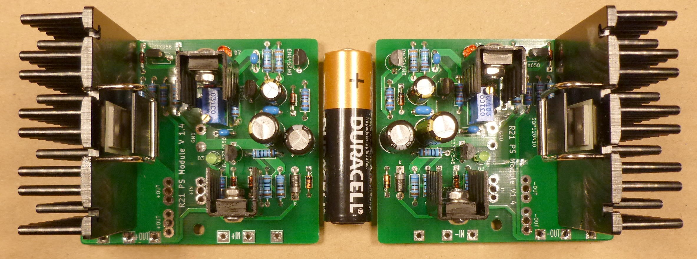
R21 is power supply add-on module that replaces resistor between two capacitors in a standard CRC power supply and transforms it in to the regulated power supply. It has high PSRR and output current, low dropout voltage, output impedance, and noise. Transient response is good and module dimensions are small.
It works, as is without any changes, from 10 to 65 V output voltage and load up to 10 A, with dropout voltage of 0.15 V for 10 A load, PSRR greater than 100 dB @ 100/120 Hz and total noise less than 3 uV. Headroom voltage is 0.5V for 10 A load.
Single rail module dimensions, including heatsink, are 70 x 60 x 38 mm.
Why I made and published this is explained here:
https://www.diyaudio.com/forums/pass-labs/376002-amplifier-extension-power-supply.html#post6759478
As I see it, the most favorable property of this regulator module is that it can be used as an upgrade on wide variety of existing power supplies and that it can be easily utilized on one DIY project and then repurposed for another one. With this add-on regulator, single power supply is upgraded to the level above dual mono PS configuration.
Measured performance:
That's all fine, but there is a catch.
You can't use regulator at 0.3 V voltage drop in the ordinary CRC power supply, as there is a substantial ripple voltage at the first capacitor in the CRC line and there is also some mains voltage variation. In example, usual 30 mF capacity will provide 1 Vpp ripple at 3 A load. Minimum drop that can be used is half the ripple voltage + min. regulator headroom: 0.5 + 0.3 = 0.8 V. Add some headroom for the mains fluctuation/voltage drop at load and, realistically, 1.5 - 2 V drop is what can be used as a minimum on A class power amplifiers.
There was some voltage drop on the resistor in the CRC chain, so only 1.5 V is lost. That shouldn't be a problem, but if you really need every volt, then replace diode rectifier bridge with active rectifier (LT4320). This will provide 1.5 V higher rectified voltage in comparison to diode bridge.
For the new designs, you can order transformer with 2 V higher secondary voltage.
Building
Complete documentation including BOM, one click shopping cart, gerbers and build guide is attached. I've made a reasonable effort to provide documentation that will be sufficient for anyone to build this module, however this project is not suitable for beginners. Design is made with through hole components, as much as possible. There are only two really easy to solder SMD components that require fine soldering tip.
Parts
Recent parts shortages postponed project for 8 months. At any moment, something from the parts list was not available. I had to find and verify suitable replacements. Situation is increasingly frustrating and it is hard to obtain all parts from only one source or at all. I've prepared one click Mouser shopping carts for easy ordering, though you'll certainly need to adjust them.
Mouser Electronics, Inc. Croatia
It works, as is without any changes, from 10 to 65 V output voltage and load up to 10 A, with dropout voltage of 0.15 V for 10 A load, PSRR greater than 100 dB @ 100/120 Hz and total noise less than 3 uV. Headroom voltage is 0.5V for 10 A load.
Single rail module dimensions, including heatsink, are 70 x 60 x 38 mm.
Why I made and published this is explained here:
https://www.diyaudio.com/forums/pass-labs/376002-amplifier-extension-power-supply.html#post6759478
As I see it, the most favorable property of this regulator module is that it can be used as an upgrade on wide variety of existing power supplies and that it can be easily utilized on one DIY project and then repurposed for another one. With this add-on regulator, single power supply is upgraded to the level above dual mono PS configuration.
Measured performance:
- 104 dB PSRR @ 100/120 Hz at 0.3 V headroom and 5 A load
- 2.5 uV total noise @ 5 A DC load or 17 nV/rtHz noise density @ 1 kHz
- 0.01 % load regulation @ delta I = 9.3 A (2 mV output voltage change for the 9.3 A load increase at 30 V output)
- 0.001 %/V line regulation @ delta V = 10 V (1 mV output voltage change for the 10 V input voltage rise)
- 40 uOhm output impedance @ 20 kHz
That's all fine, but there is a catch.
You can't use regulator at 0.3 V voltage drop in the ordinary CRC power supply, as there is a substantial ripple voltage at the first capacitor in the CRC line and there is also some mains voltage variation. In example, usual 30 mF capacity will provide 1 Vpp ripple at 3 A load. Minimum drop that can be used is half the ripple voltage + min. regulator headroom: 0.5 + 0.3 = 0.8 V. Add some headroom for the mains fluctuation/voltage drop at load and, realistically, 1.5 - 2 V drop is what can be used as a minimum on A class power amplifiers.
There was some voltage drop on the resistor in the CRC chain, so only 1.5 V is lost. That shouldn't be a problem, but if you really need every volt, then replace diode rectifier bridge with active rectifier (LT4320). This will provide 1.5 V higher rectified voltage in comparison to diode bridge.
For the new designs, you can order transformer with 2 V higher secondary voltage.
Building
Complete documentation including BOM, one click shopping cart, gerbers and build guide is attached. I've made a reasonable effort to provide documentation that will be sufficient for anyone to build this module, however this project is not suitable for beginners. Design is made with through hole components, as much as possible. There are only two really easy to solder SMD components that require fine soldering tip.
Parts
Recent parts shortages postponed project for 8 months. At any moment, something from the parts list was not available. I had to find and verify suitable replacements. Situation is increasingly frustrating and it is hard to obtain all parts from only one source or at all. I've prepared one click Mouser shopping carts for easy ordering, though you'll certainly need to adjust them.
Mouser Electronics, Inc. Croatia
Attachments
Circuit description
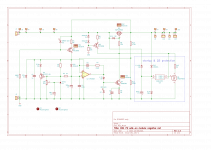
Regulator is ordinary and simple super regulator in the LDO configuration with MOSFET as a pass element and op amp as an error amplifier. For voltage reference, TL431 is used along with RC noise filter. Before you ask, LED reference with elaborated temperature compensation (temp. dependent CCS) was evaluated, but TL431 won as a simple and good enough solution. Shunt regulator (Q1, Q2) tracks voltage reference by +4 V (D3 + Q2 Vbe) and provides supply with always enough headroom for op amp and voltage reference. Amusing benefit of this voltage tracking is that R2 becomes CCS. Q3 is CCS that provides stable gate drive and Q4 load. Gate voltage is regulated by Q4 and op amp. Q4 & Q3 pair can be considered as another shunt regulator. LED diode D7 and R9 serve as a current limiter for condition when Q4 base is at op amp max. output. In example, this will happen if input voltage is below set output voltage. Without current limiting, at high output voltages Q4, D8 or R8 could be burned. Red LED D7 is also a visual indicator of too low input voltage. If input voltage is below set output voltage, at output voltages from 18 V and up, LED is slowly flashing. At voltages below 18 V it is constantly lit.
Biggest development challenge was to provide that regulator tolerates large capacitor banks at its output, meaning that it survives huge inrush currents at startup, where in combination with high Vds for enough long time (inevitable condition with voltage reference RC filtering), MOSFET SOA is heavily violated. I’ve burned 8 MOSFETs while exploring limits.
Never mind that those huge capacities are totally unnecessary and wasted with this regulator, but they are usually there in every unregulated CRC power supply. If you can, replace output capacitors bank with recommended smaller value and put them to better use in another project. Those cap banks will be completely overrun by regulator low output impedance and any “sound signature” they might have will vanish.
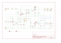
Current limiting was evaluated in simple and not so simple versions and discarded. Instead, problem was addressed from the opposite side with solution that provides lowest Rds On and Vds of MOSFET, from the first milliseconds of PS startup till output capacitors are charged and voltage reference RC filter reaches its nominal voltage. Q6 is depletion mode device DN2540, which serves as a current sink that, on startup, brings MOSFET gate voltage down to necessary level for full on state. D9 is current regulating diode with 1.5 mA constant current. With C7 and D11 it forms timing circuit that, after 3 s, switches on optocoupler and turns off Q6, thus putting regulator in a normal working condition. This solution also enabled option to supply voltage reference and op amp from the regulator output, in the Jung regulator fashion, which adds several dB to PSRR at lowest frequencies.
Only negative consequence of this solution is short period of unregulated PS output and slight overvoltage after power on.
For design validation, supplied from 680 VA single rail transformer with no soft start and with synchronized rectifier, regulator was switched on/off more than 500 times in a row at 7 s on/7 s off sequence with 70,000 uF at output and constant 5A load (current sink) active from 3 V output voltage and up.
For final test of resilience, powered on regulator set at 30 V output, was short circuited with solid copper wire. After smoke has cleared, inspection showed that wire was burned, but not completely melted, along with evaporated part of wide PCB track at MOSFET input side. PCB was repaired with solder bridge and regulator measured again. All parameters (PSRR, noise, output impedance, transient response) were spot on.
Yes, this was an extreme test (please refer to the diyaudio motto), but I’m uncomfortable publishing design for which I’m not sure if it will survive most of conditions in variety of existing CRC supplies for audio.
Regulator is ordinary and simple super regulator in the LDO configuration with MOSFET as a pass element and op amp as an error amplifier. For voltage reference, TL431 is used along with RC noise filter. Before you ask, LED reference with elaborated temperature compensation (temp. dependent CCS) was evaluated, but TL431 won as a simple and good enough solution. Shunt regulator (Q1, Q2) tracks voltage reference by +4 V (D3 + Q2 Vbe) and provides supply with always enough headroom for op amp and voltage reference. Amusing benefit of this voltage tracking is that R2 becomes CCS. Q3 is CCS that provides stable gate drive and Q4 load. Gate voltage is regulated by Q4 and op amp. Q4 & Q3 pair can be considered as another shunt regulator. LED diode D7 and R9 serve as a current limiter for condition when Q4 base is at op amp max. output. In example, this will happen if input voltage is below set output voltage. Without current limiting, at high output voltages Q4, D8 or R8 could be burned. Red LED D7 is also a visual indicator of too low input voltage. If input voltage is below set output voltage, at output voltages from 18 V and up, LED is slowly flashing. At voltages below 18 V it is constantly lit.
Biggest development challenge was to provide that regulator tolerates large capacitor banks at its output, meaning that it survives huge inrush currents at startup, where in combination with high Vds for enough long time (inevitable condition with voltage reference RC filtering), MOSFET SOA is heavily violated. I’ve burned 8 MOSFETs while exploring limits.
Never mind that those huge capacities are totally unnecessary and wasted with this regulator, but they are usually there in every unregulated CRC power supply. If you can, replace output capacitors bank with recommended smaller value and put them to better use in another project. Those cap banks will be completely overrun by regulator low output impedance and any “sound signature” they might have will vanish.
Current limiting was evaluated in simple and not so simple versions and discarded. Instead, problem was addressed from the opposite side with solution that provides lowest Rds On and Vds of MOSFET, from the first milliseconds of PS startup till output capacitors are charged and voltage reference RC filter reaches its nominal voltage. Q6 is depletion mode device DN2540, which serves as a current sink that, on startup, brings MOSFET gate voltage down to necessary level for full on state. D9 is current regulating diode with 1.5 mA constant current. With C7 and D11 it forms timing circuit that, after 3 s, switches on optocoupler and turns off Q6, thus putting regulator in a normal working condition. This solution also enabled option to supply voltage reference and op amp from the regulator output, in the Jung regulator fashion, which adds several dB to PSRR at lowest frequencies.
Only negative consequence of this solution is short period of unregulated PS output and slight overvoltage after power on.
For design validation, supplied from 680 VA single rail transformer with no soft start and with synchronized rectifier, regulator was switched on/off more than 500 times in a row at 7 s on/7 s off sequence with 70,000 uF at output and constant 5A load (current sink) active from 3 V output voltage and up.
For final test of resilience, powered on regulator set at 30 V output, was short circuited with solid copper wire. After smoke has cleared, inspection showed that wire was burned, but not completely melted, along with evaporated part of wide PCB track at MOSFET input side. PCB was repaired with solder bridge and regulator measured again. All parameters (PSRR, noise, output impedance, transient response) were spot on.
Yes, this was an extreme test (please refer to the diyaudio motto), but I’m uncomfortable publishing design for which I’m not sure if it will survive most of conditions in variety of existing CRC supplies for audio.
Attachments
PSRR
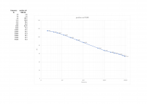
Meh, only 104 dB PSRR. There are regulators with 30 dB more! Why did I even bother?
Ah yes, because those regulators have low nominal output current and high dropout voltage.
It is good to put those abstract PSRR numbers in some proportion. In example, 1 Vpp ripple will be, at 104 dB PSRR, reduced to 2 μV rms at the regulator output. You can’t hear that even sticking your head into 110 dB/W horns. It’s not even easy to measure that.
In comparison, CRC supply will provide 30 dB PSRR and 12 mV output ripple. Good Cap Mx will provide about 60 dB PSRR and 0.3 mV ripple.
Measurement was done using custom build signal injector capable of providing output of 10 – 35 V and 10 A up to 100 kHz. With precisely set ripple voltage and frequency, PSRR level was measured with 1000x LNA, Focusrite solo ADC and REW software.
Before measurement, very thorough calibration was done checking measured level through complete 20 Hz – 95 kHz range, using RMS voltmeter precise up to 100 kHz with max. 0.8 % error, signal generator and precise voltage divider. Result was my own calibration table with corrections in dB for any frequency of interest. I must say that REW autocalibration feature with loopback connection is not good enough above 45 kHz.
Attachments
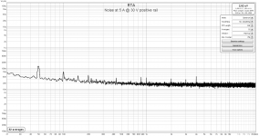
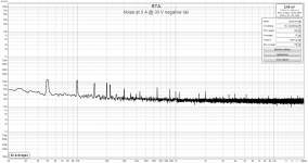
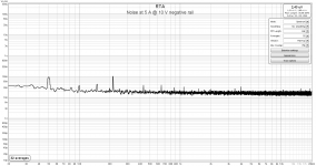
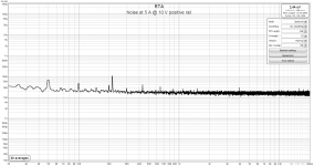
Noise
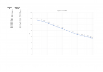
Measurement was done using Samuel Groener’s 60 dB LNA and REW software. Noise level is almost the same for any output voltage level, as error amplifier operates at a fixed gain.
Not a world record breaking performance but a very good one, even suitable for preamplifiers.
Measurement was done using Samuel Groener’s 60 dB LNA and REW software. Noise level is almost the same for any output voltage level, as error amplifier operates at a fixed gain.
Not a world record breaking performance but a very good one, even suitable for preamplifiers.
Attachments
transient response
Why are regulated PS so rare in the power amplifiers?
I’ve found here opinions that main problem is bad transient response spoiling sound and/or regulator complexity, size and dissipation. R21 module design takes in the account those concerns. Transient response is good. It is proportional only to the speed of load change and doesn’t change with load or output voltage level. It is also almost the same with 470 uF or 33 mF output capacitor.
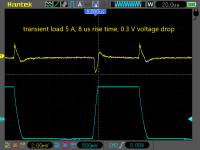
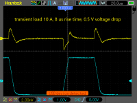
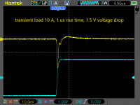
Transient response was measured with 8 µs rise time signal, which roughly corresponds to 20 kHz audio signal. Blue oscilloscope trace is voltage measured at 0.33 Ω resistor in the used active load.
Transient load with 1 µs rise time, has expected ringing at very low voltage drop, but at 1.5 V response becomes very good, even for such extreme transient.
Dimensions of 60 x 70 mm, including heatsink, provide that regulators can fit to existing designs. Low dropout means low dissipation. Integrated heatsink is good up to 10 W dissipation at 31 °C temperature rise. In general, integrated heatsinks are good for usual 3 – 3.6 A combined channels load found in the First Watt clones and similar. For higher dissipation, external heatsink can be easily used.
Why are regulated PS so rare in the power amplifiers?
I’ve found here opinions that main problem is bad transient response spoiling sound and/or regulator complexity, size and dissipation. R21 module design takes in the account those concerns. Transient response is good. It is proportional only to the speed of load change and doesn’t change with load or output voltage level. It is also almost the same with 470 uF or 33 mF output capacitor.
Transient response was measured with 8 µs rise time signal, which roughly corresponds to 20 kHz audio signal. Blue oscilloscope trace is voltage measured at 0.33 Ω resistor in the used active load.
Transient load with 1 µs rise time, has expected ringing at very low voltage drop, but at 1.5 V response becomes very good, even for such extreme transient.
Dimensions of 60 x 70 mm, including heatsink, provide that regulators can fit to existing designs. Low dropout means low dissipation. Integrated heatsink is good up to 10 W dissipation at 31 °C temperature rise. In general, integrated heatsinks are good for usual 3 – 3.6 A combined channels load found in the First Watt clones and similar. For higher dissipation, external heatsink can be easily used.
Attachments
Output impedance
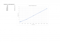
Measurement was done using active load driven by signal generator, with 5 A & 10 A square wave load and 1000x LNA in front of oscilloscope, to observe voltage drop between no load and full load condition. That way, measurement resolution could go, if necessary, down to 2 µV/div.
Impedance is measured directly at the regulator output. Even wide and short PCB track from regulator to output changes impedance by hundredths of μΩ.
Measured output impedance of R21 module alone is at very low levels, so PSU output impedance will actually consist of combined PSU interconnection and wiring impedances, which are orders of magnitude greater than regulator output impedance.
Attachments
Sanity check – is this the right project for you?
Check how you fare:
If answer to the any of above questions is negative, you are better to skip this project.
Check how you fare:
- You are fine with RTFM and don’t jump in to the action without reading documentation (at least twice).
- You are not confused with aligning diodes, transistors and capacitors according to the print on the PCB silkscreen.
- You know how to measure basic electrical values like voltage, resistance and current at the right spot of populated PCB.
- You have several successful DIY projects behind you.
- You have some experience with soldering SMD components.
- You have soldering iron with temperature control and several tips that include very fine one (0.3 mm) standard (about 1 mm or so) and a fat one (chisel or knife).
- You have an oscilloscope. Any cheap (30 $) single channel model will do.
- When stuck, you tend to ask for help instead of doing something in hope it will turn out just fine.
If answer to the any of above questions is negative, you are better to skip this project.

Everytime I use active regulators: I do listen the characters of the transes - and other parts: overcast, cloudy, disembodied, contourless...
I do prefer CLC-lines. I would use any L.
And, what were PSRR, transient response, output impedance in the whole audio bandwidth and noise of those regulators that you did listen to?
Which modulations are more audible;-?
So, you only know that you were not satisfied with regulators that were not measured for their important parameters.
The thing is, good regulated PS will not allow any modulation of its output by load change. That is visible on transient measurement screenshots.
There are many PS available here, but mostly without any measurement. So, we must accept them at the face value and hope all will be good.

tombo56, this may be just what I need to go further down the road of understanding some PSU topologies and perhaps improve my existing "standard" FW PSUs.
I have more reading to do, but if/when I order some boards and parts to try out, I'll certainly post back.
This community never ceases to amaze and delight me.
Thanks for sharing your design, your thoughts, and your documentation!

I have more reading to do, but if/when I order some boards and parts to try out, I'll certainly post back.
This community never ceases to amaze and delight me.
Thanks for sharing your design, your thoughts, and your documentation!
Have you done any subjective listening on some amps?
I just remembered and found again discussion where is mentioned what subjectively happens when you improve amplifier PS.
https://www.diyaudio.com/forums/power-supplies/374100-maximal-capacitor-value-solid-power-amps-2.html#post6706855
Increasing capacitance effectively decreases output impedance, ripple and noise (rectification harmonics that are quite high till 1 kHz in an ordinary CRC) and improves transient response. It is interesting that with every capacitance doubling, distinctive improvement in sound was perceived.
With regulated linear PS, it is as you have put 100 or more big capacitors in parallel and even better than that. There will be change in sound of the amplifier.
It is not to say that it will be better for everyone. Maybe one just likes soft bass caused by inadequate and sagging PS, or warm colored midrange caused by specific ESR/ESL properties of boutique capacitors. Audio is really a playground with specific tastes of an individual.
- Home
- Amplifiers
- Power Supplies
- An arguably better replacement for the resistor in a CRC power supply - R21 PS module