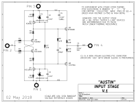
As usual, great work. Did you check difference in BC vs. ZTX case orientation? Silkscreen is for ZTX.Hopefully no magic smoke is released during the power verification, I waited a year to accumulate the parts and don’t want them to go Poof💥!!
MOSFET’s are incredibly robust and, during development, survived multiple short circuits resulting with melted wires, evaporated PCB tracks and a lot of smoke.
Hopefully, it will not come to that.
")
If you have regulated bench PS, just connect it to one CRC board AC input and gradually rise output voltage.
Mine LTSpice simulations are in disarray with many varying options and not fit for posting.@tombo56 do have spice simulations for the positive and negative side? Would you mind posting them?
Thanks, Mo
Yes, the BC components would seem “backwards” in the ZTX locations.….Did you check difference in BC vs. ZTX case orientation? Silkscreen is for ZTX….
Hfe ‘A’ grade is installed here.
‘B’ and ‘C’ are used as per BOM for 327/337 replacements.
I will use my bench supply as you recommended, a bit safer than a variac in case of a problem.
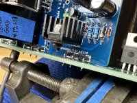
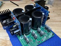
It’s a good night without fireworks at the bench! Besides a reversed diode (D5) on a negative regulator, all R21 modules powered up drama free. The red led (D7) blinks when voltage drop isn’t sufficient and falls out of regulation.😉
On to the next phase…..
On to the next phase…..
Attachments
Welcome to the exclusive club of only two forum members having this voltage regulator.On to the next phase…..
Hopefully it will turn better in the future.
If your next step is soldering regulators to the CRC boards, I would propose the following way:
There are 6 connection points per regulator, aligned with CRC board holes provided for power resistors. Connecting 4 is enough for stable mounting but 6 is better. I used 0.8 mm cutoff wires from diodes. IIRC, 1 mm is max. what would fit to CRC board holes. First, all 6 straight wires were soldered to regulator PCBs. Then, all were bended 90° to be parallel with regulator PCB. Ground wire was soldered from the regulator bottom side and left with excess length.
Next, whole regulators was inserted to CRC PCB aligning/bending wires as necessary. Then, whole CRC PCB + regulators assembly was flipped over and left resting on regulator modules for easy soldering.
Grounding wires should be 1 – 1.5 mm2. Solder both to sides of the same middle GND faston. Ground wires should be short but leave enough length for routing around possible output capacitors.
Glad to join the exclusive club Tombo, but it’s more fun when the numbers grow! This darn mosfet is a roadblock!
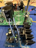
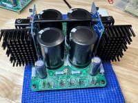
Thanks for the install tips but I went with right angle pin headers in all 6 positions. Very solid as is, I installed a cross brace between the pair of R21 modules for added rigidity.
Prasi’s 2mm thick boards are a perfect foundation to carry the extra weight without flexing. This is one Bad*SS psu!! Should be named Mad Maxx Regulator 😆

!Thanks for the install tips but I went with right angle pin headers in all 6 positions. Very solid as is, I installed a cross brace between the pair of R21 modules for added rigidity.
Prasi’s 2mm thick boards are a perfect foundation to carry the extra weight without flexing. This is one Bad*SS psu!! Should be named Mad Maxx Regulator 😆
Attachments
Vunce, you are a genius - a great implementation, well built.
It is possible that Mouser didn’t play fair with latest MOSFETs shipment and ignored small customers.Now if only I could get my hands on some of those mosfets, I would copy that!
@Tombo. Just looking at parts to build these regs.
Are there any alternatives to the SUP70101EL , even with slightly different performance - none available till Aug 24 (if you can believe that)
XTX958 and 658 are not available till Oct 2024 - what are alternative's?
SQP120N10 is end of life and not many left - again any alternatives?
VOM1271T available Jan 2024.
Maybe if there were more readily available parts used then more people could build this design - what are your thoughts?
As far as I know, they do not shift priority based on order amounts or customer size. However, if Customer A has already placed an order for (make up a huge number) ... they get all their pieces until the order is fulfilled, then it moves to Customer B and on down the line by order timing. Quantity of the order nor the size of the customer play a role based on what I was told. Customers cannot amend an existing order to increase quantities. Customers can decrease the quantity or cancel. i.e. they can't pay Mouser for 20 pieces to hold a "spot in the queue" and then a month before they're supposed to be available increase the order and pay for 100,000 parts. I've also posted previously re: what they've told me over the phone re: what would happen if something was needed for a military order. Less than ideal, but perfectly fair. They also would not disclose (to me anyway) how many pieces they actually received (if any) from the order that Vishay showed arriving in November and/or if those parts were re-directed. They would not disclose to me how far down in the queue I was nor the total number of pieces on backorder ahead of me. All this is hearsay based on conversations with a few customer service reps.It is possible that Mouser didn’t play fair with latest MOSFETs shipment and ignored small customers.
I wouldn't count on August either, but... who knows...Are there any alternatives to the SUP70101EL , even with slightly different performance - none available till Aug 24 (if you can believe that)
Maybe just maybe you might think about instigating a community re-design.
A re-design which replaces the currently unobtainable power transistor(s) with something almost as good but widely available today. Then, as they say, "as long as you've got the hood up anyway," you might also think about replacing the hard-to-find opamp with something almost as good but widely available today. And since the circuit doesn't actually require galvanic isolation (the input side and the output side of the photovoltaic SSR are shorted together!), you might also think about reimagining that piece of the circuit to eliminate the costly VOM1271T.
Not meant as a criticism -- it's merely a possibility, which provides an option to achieve working circuit boards many months before Mouser restocks all parts in the present BOM.
Also not meant as a volunteer enlistment.
Huh, didn’t I give some replacements at post #67.Are there any alternatives to the SUP70101EL , even with slightly different performance - none available till Aug 24 (if you can believe that)
XTX958 and 658 are not available till Oct 2024 - what are alternative's?
SQP120N10 is end of life and not many left - again any alternatives?
SQP120N is available, so no need for replacement search.
SUP70101 remains the problem. Luckily (actually a miracle) there is a suitable replacement at Mouser’s stock: SUP60061EL-GE
https://hr.mouser.com/ProductDetail/Vishay-Siliconix/SUP60061EL-GE3?qs=TuK3vfAjtkWzs5EzO2t/6w==
I’ll have to order several myself to determine optimal compensation resistor value. It changes with any different MOSFET input capacitance.
For negative regulator order SQP120N10-09_GE3
https://hr.mouser.com/ProductDetail/Vishay-Siliconix/SQP120N10-09_GE3?qs=Nn1VXUNwu%2B/dh2XamFxneg==
You meant not as some unknown volunteer but me?Maybe just maybe you might think about instigating a community re-design.
If there will be a redesign I would rather design complete PS board with active rectification and regulators on-board. It would be limited to 10-36 V output, but performance would be better.
This regulator has some very good properties that I would like to keep: it works perfectly stable from zero output capacitance to 100 mF or more. It keeps regulation at 0.1 V/10 A and has exemplary transient response at just 0.3 V headroom. Not easy to get and various opamps and MOSFETs were tried on the bench till performance was that good. LTSpice was not good enough for actual choices to be made.
Redesign would be a serious task.
- Home
- Amplifiers
- Power Supplies
- An arguably better replacement for the resistor in a CRC power supply - R21 PS module