More sims
I've simulated the following circuit :
Click here for schematic
This has all the previously mentioned VAS'es, all loaded by a current source which looks like their twin.
They are fed from a current source of 70K impedance and are studied open-loop. This means I had first to close the loop, note the base current, then add a bias source on the base so the output of the VAS is about 0V open-loop.
Thus we can simulate VAS open-loop response, something which is utterly impossible to do outside of a simulator.
Curves coming in shortly.
And here are the VAS transimpedances (Re=100) :
These are d(VAS collector voltage)/d(VAS base current).
normal 4.7 MOhm
cascode 48 MOhm
hawksford 1420 MOhm
baxandall 76 MOhm
bax+hawk 28200 MOhm
Now I'll plot normalized output voltages with all VAS'es swinging +- 20V (by dividing the respective input currents by these factors) and study the open loop output distortion.
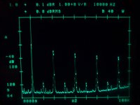
Distortion
I have posted too many graphs already, so I will just talk about the distortion measurements...
In OPEN LOOP, the surprise is that all VAS'es perform about the same. ie When they put out a +-16V output sine, they all add the same amout of distortion (well, not exactly the same, but it's close).
Here I give the distortion signal in Vpp :
Normal : 1.4V
Normal cascoded : 1.5V
Hawksford : 1V
Hawksford+Baxandall : 1.2
Baxandall : 0.5
... and I added a simple Darlington which performs as well as the Baxandall in this respect !
Note that all these stages distort a lot ! The normal one has distortion at -26 dB from the main signal (at 1k).
So, the large difference in distortion using the Baxandall does not come from it behaving a LOT better, it simply comes from it having more gain... and when you study it closed-loop, feedback masks everything. I wonder if it behaves better than a simple Darlington.
Back to the start
Now let's go back to the subject of this post, namely the Aussie amp. Why does it sound good, and why did the designer use such a complicated (and symmetrical) VAS ?
I do think that fully symmetrical amps are a bad idea. With two input stages, you never know where your operatng point is, and both have to be very well matched. So I do agree on the single input stage.
But why the symmetrical VAS ?
He could have done something like that and save on complexity :
Why did he not do it ? Why did he prefer the symmetrical VAS'es and why does it sound so good according to you ?
By the way, I realized this schematic is more or less the Otala amp (see schematic here). But the otala amp has reduces OL gain because of resistors going from VAS collector to ground, which was supposed to fight TIM, which does not exist, and just crippled the sound.
As for using two VAS stages, this may be to save on power supplies. If the amp is to output voltages close to the rail, the VAS must be able to go close to the rail. Hence the necessity for some voltage shifting, which is done here by the two VAS'es. But if we used two power supplies, we could use only 1 VAS stage (skipping the middle one in my schematic) which gives us more or less the Kaneda amp :
And, note also that using a symmetrical VAS like the Australian Amp does needs two stages as the currents must be shifted from the upper to the lower rail.
Now let's go back to the subject of this post, namely the Aussie amp. Why does it sound good, and why did the designer use such a complicated (and symmetrical) VAS ?
I do think that fully symmetrical amps are a bad idea. With two input stages, you never know where your operatng point is, and both have to be very well matched. So I do agree on the single input stage.
But why the symmetrical VAS ?
He could have done something like that and save on complexity :
An externally hosted image should be here but it was not working when we last tested it.
Why did he not do it ? Why did he prefer the symmetrical VAS'es and why does it sound so good according to you ?
By the way, I realized this schematic is more or less the Otala amp (see schematic here). But the otala amp has reduces OL gain because of resistors going from VAS collector to ground, which was supposed to fight TIM, which does not exist, and just crippled the sound.
As for using two VAS stages, this may be to save on power supplies. If the amp is to output voltages close to the rail, the VAS must be able to go close to the rail. Hence the necessity for some voltage shifting, which is done here by the two VAS'es. But if we used two power supplies, we could use only 1 VAS stage (skipping the middle one in my schematic) which gives us more or less the Kaneda amp :
An externally hosted image should be here but it was not working when we last tested it.
And, note also that using a symmetrical VAS like the Australian Amp does needs two stages as the currents must be shifted from the upper to the lower rail.
Simulations
From my simulations, the last diff stage could be like it is in the Aussie amp, or a simple diff stage feeding a current mirror, and the distortion would be about the same.
Besides, the distortion profiles look about exactly the same.
Thus either the diff+current mirror VAS sounds as good as the symmetric diff, or we have to investigate beyond THD (guess..)
Peufeu,
Brilliant, inspired work!! Congratulations; you are reaching into the soul of amplifier design.
I would be interested in your thoughts on the use of lag compensation on these VAS. While the higher Zout of some of the designs gives higher gain, and thus more feedback factor, lag compensation, all other things being equal, will have more crippling effects.
It seems whatever you do, you come back to a similar outcome.
I mention this because in all my tuning of power amps I have noticed that the voltage amplifier characteristics of great importance are the speed of the device, the rail voltage, and the lag compensation. I have tried conventional, cascode and Rush cascode, driven differentially from collector resistors. All these critical parameters interact, and more lag compensation progressively cripples the sound. Less is best, and to my reckoning, the design which can tolerate the least lag compensation seems to sound the best.
Merci beaucoup!!
Cheers,
Hugh
distortion
I'm finding the Aussie amp's VAS (and Otala, too) distort more than the good old Lin (and symmetrical Lin) when using a VAS collector impedance of 1Meg.
I am therefore perplexed and will go for some biking after I eat...
Hugh, do you have any idea to explain the supposedly exceptionnal performance of that amp ?
Thank you Hugh...
> I would be interested in your thoughts on the use of lag compensation on these VAS. While the higher Zout of some of the designs gives higher gain, and thus more feedback factor, lag compensation, all other things being equal, will have more crippling effects.
Well getting unreal collector impedances in the VAS is not really useful because the output stage which comes after that will have a low impedance anyway. Maybe not that low if we use a follower, but not that high either. I'd say an output stage with follower, driver and output transistor will look like ... maybe a few megohms at DC, and above that, it'll look like crap anyway thanks to parasitic caps.
But maximizing VAS transimpedance still has its uses as it lets us learn which configurations are vulterable to the coupling through Cbc which is nonlinear and magnified by Miller effect... and it is still good to have a VAS which distorts less itself than what the output stage does to it...
All these loop systems always turn around as you say : if more gain = more distortion, feedback is useless.
> I mention this because in all my tuning of power amps I have noticed that the voltage amplifier characteristics of great importance are the speed of the device, the rail voltage, and the lag compensation. ...
What's Rush Cascode ?
> I have tried conventional, cascode and Rush cascode, driven differentially from collector resistors. All these critical parameters interact, and more lag compensation progressively cripples the sound. Less is best, and to my reckoning, the design which can tolerate the least lag compensation seems to sound the best.
Two thoughts :
Less compensation = the amp was faster to begin with, hence it'll have more feedback, less distortion.
And any parasitic effects in the compensation cap are magnified out of proportion by Miller effect :
When the operating point is defined by feedback, you only need to send very little current in the VAS base to make it swing the full voltage swing of the amp?
Say if your amp swings +- 40V, VAS collector impedance is 1Meg, current gain is 500, thus VAS transimpedance is 500 Meg (or 500 V/uA !) thus a full swing of 80V just needs 0.16 uA (not counting current going into Cdom at HF). It's even higher if your VAS has two transistors.
Now imagine your cap has a little dielectric absorption or (hell) microphonics in it, imagine if it generates only 0.16uA of spurious current this will be equivalent as a full swing... it will be hidden by feedback of course, but its contribution do distortion in the VAS and Input stages will be exactly the same as if it had been part of the music signal...
Hence the need for a good quality cap for your VAS. It's basically the part in the whole amp whose tiny imperfections are the most magnified... I usually use Styroflex...
That's what I think, what do you think about this ?
We are looking for the highest collector impedance, because this means less parasitic currents running through non-linear capacitances.
But what price is being paid to reduce this source of distortion? To tackle this the circuits use more amplifying devices, each of which is grossly non-linear in its primary signal path, let alone its parastic paths.
Typical designs use a single device and swamp the Cbc with a parallel linear cap, as you know. The cap also serves to slow the amp down and keep it stable. This works extremely well provided other problems in the system have been correctly resolved.
My question is how much distortion is being generated with the enhanced VAS circuits once they have the same lag C across them as a simple VAS?
Excellent work Peufeu,
The next step after maximizing VAS gain is figure out how to use it to improve overall amplifier distortion (at least for us simulator jockeys!), “throwing away” the gain in a lag C (and sometimes a parallel R) to ground seems wrongheaded although it is seen some well regarded amps
“Miller” local feedback C around the VAS is the most common compensation technique and high gain inside the loop improves performance by reducing VAS output impedance where it often interfaces to nonlinear output driver impedance – such as directly driving the output fet gates which have very nonlinear Cin
Two less pursued options are Cherry’s moving the feedback C to enclose the output stage and 2 pole compensation (which work particularly well together in my sims)
Cherry’s compensation is rarely seen in discrete audio amps, a number of op amps use the technique; see the 100W TDA7293 data sheet for a strong "proof of principle" that the idea is viable in audio power amps, see also: http://www.ne.jp/asahi/evo/amp/J200K1529/report.htm fig 6&7 (not strictly “Miller” compensation but enclosing the output stage does improve the dist #)
Self briefly explores 2 pole compensation around the VAS stage in his book, this technique begins moves beyond the absolute gain stable feedback region but not very far, and higher order conditionally stable control loop techniques have been in use for over half a century, some threads here have tried to adress this
the TDA7294 block diagram shows the Cherry stlye compensation better: http://us.st.com/stonline/books/pdf/docs/1057.pdf
Re: Distortion
I have seen a small mosfet in this position in the john linsley hood
100W Mosfet o/p amp and use one myself in an adeptation of his simple class A amplifier.
what do we think about this option in the context of the research above ?
mike
peufeu said:So, the large difference in distortion using the Baxandall does not come from it behaving a LOT better, it simply comes from it having more gain... and when you study it closed-loop, feedback masks everything. I wonder if it behaves better than a simple Darlington.
I have seen a small mosfet in this position in the john linsley hood
100W Mosfet o/p amp and use one myself in an adeptation of his simple class A amplifier.
what do we think about this option in the context of the research above ?
mike
see "Gain Stage Investigations" Electronics World, july '98 by Hood
he shows a final config of the VAS as a mirrored diff stage driving a small mosfet common source (no degeneration) that is cascoded with a bipolar to get the max gain from high input impedance at the input to the VAS stage as he assumes a constant load on the VAS from the output stage
the high output Z available from the elaborated cascodes and super-pair enable higher gain if output stage drive impedance can be increased with further buffering - a point that i think can be seen in http://www.ne.jp/asahi/evo/amp/J200K1529/report.htm going from fig 7 to fig 13 (lots of mods but i think the performance couldn't get near these levels without the buffering of the output fet gate impedance)

Hi jcx thanks for your info.
I'm interested in your articles. Can you post relevant schematics, or better, scan them and send me files (I'll give you my email) so I put them on my website for all to see. This would be cool.
About using Mosfets in VAS :
I have simulated this a long time ago while writing my pages on thermal distortion. It had interesting side-effects, notably that current-driving a mosfet gives nearly infinite gain at DC... hence the current mirror driving a MOSFET is a good idea I think. And the cascode is a must, too.
To mikelm :
Can you post schematics ? How does it sound ?
Other thoughts :
Reminder : voltage-driven VAS is driven by a voltage (!) and its gain is controlled by an emitter resistor. Current-driven VAS is driven by a current mirror and its gain is more or less beta, the emitter resistor playing more obscure roles. Both VAS are influenced by colelctor impedance effects.
Generally I think voltage-driven VASes distort more for the following reasons :
- The current mirror balances the input stage better (so all the nice properties in the diff pair can apply). Hence not using a current mirror will distort more in the input stage.
- For the same amount of gain to be generated, it is a lot easier to use Beta, which is linear over a wide range of currents, than to make a transimpedance amp (voltage-driven emitter follower) whose Vbe varies a lot. I had simulations showing that for the same gain, amplifying current directly distorted a lot less than going from I -> V -> I through base and emitter resistors.
- While Beta does vary with temperature, Vbe varies a lot more and a few degree's change in the VAS core transistor will have more influence if it is voltage-driven than current-driven (this depends on the actual gain and emitter degeneration, though).
Thus I'll stick with the classical current-driven VAS : diff stage -> current mirror -> VAS -> conversion to voltage in VAS collector impedance.
Playing with the VAS'es again, some of them (the cascoded ones) have a small signal gain which is rather constant with output voltage, whereas the non-cascoded ones (even Baxandall super pair) have a small-signal gain which varies (sometimes a lot) according to large-signal amplitude.
Even the first pole frequency changes according to the output voltage...
I don't like this, even if it's hidden by the Dominant Pole Compensation Feedback cap...
Hence : Cascode is Good. Plus it keeps the VAS transistor at low dissipation so we have more freedom in choosing it.
Hell we could even use JFET's !
Interesting results you've presented here peufeu. Nice work!
One very intriguing point you've raised is that the distortion of these stages without the compensation capacitor is very nearly the same. Let's assume we're going to pick the gain-bandwidth product of the amplifier, and that we have already done this by fixing the input stage gm and Miller compensation capacitor C at some value such that gm/C gives us the desired gain-bandwidth product. If we consider the Vas by itself as a feedback amplifier, this says that for a given C, the Vas configuration that gives the largest loop gain will have the lowest distortion (since they are all very similar without feedback). By loop gain, I don't mean the overall loop gain of the amplifier, but rather the loop gain of just the Vas by itself, in which the Miller capacitor forms the feedback path.
Much as I love playing around with SPICE, I think that it is very good at telling "what" is going on, but not as good at telling "why". In playing around with this a bit using a simplified model of the Vas and a plain old pencil and paper, I think I stumbled onto something that could help explain a bit of the "why" and can lead to some simple rules of thumb for reducing Vas distortion.
Let's assume a simple linear model of the Vas. Let's say the source impedance (that is, the output impedance of the diff amp) is Zs. Let's also assume the open-loop input impedance of the Vas is Zin. Further, let's assume the input voltage across Zin is Vin. We can then assume the short-circuit output current is given by gm*Vin. Then the open-loop output impedance Zout is placed across this current source, and a load ZL is placed in parallel with it. The compensation capacitor is placed from output to input of course.
We can compute the loop gain by placing a test current source IT in place of the dependent source gm. The loop gain is given by:
Loop_gain = gm * Vin / IT
using standard feedback amplifier/oscillator analysis techniques. This allows us to "unwrap" the feedback system, so to speak. To further simplify this, let:
Za = Zs || Zin ( || = "in parallel with")
Zb = Zout || ZL
When we do this analysis, which ends up being pretty simple, we get the following result:
Loop_gain = (sC * gm * Za * Zb) / (1 + sC * (Za + Zb))
Now suppose the frequency is chosen large enough such that the "1 +" in the denominator can be neglected. In this case, the loop gain above the dominant pole becomes proportional to the parallel combination of Za and Zb. I don't think it's much of a secret that the maximum ZL and maximum Zout give the highest Vas loop gain. But something that for me was less intuitive is that the maximum Zs and maximum Zin also give the highest loop gain. So this says that the optimum configuration is one with a current mirror at the diff amp outputs (giving a high Zs), and something like an emitter follower or source follower at the input (gving a high Zin). Combine this with a Hawksford cascode and high-impedance buffer preceding the output stage and you're doing about the best that can be done, I think.
... and I git an equation that is too complicated to post.
However, I don't agree with your need for high VAS input impedance...
As the VAS is fed from a current source (ie. a high impedance collector) it makes sense to maximize this current source impedance (by using a current mirror) so it behaves more perfectly.
However, the VAS output is proportional to current entering its base, thus we must minimize VAS input impedance to get more gain... this seems logical to me.
What's important is not the VAS gain after Cdom is applied, rather its gain before. As Cdom linearizes the thing, the VAS must have the highest possible gain before Cdom is applied...
Besides, Cdom feedback works well if the VAS base is at a fixed potential, because the error signal which is a current going through Cdom is Vout/ZCdom (ZCdom is the cap's impedance at a given frequency).
Augmenting the VAS base input impedance (say, by using emitter resistors, or even a base resistor) would augment the VAS gain once Cdom is applied, but only because it would divert some of the current going through Cdom back into the input stage, hence not using for what it was supposed to be, ie. feedback around the VAS...
So yes, you may get more gain with a higher input Z, but that's at the expense of feedback, ie. just as if you had used a lower Cdom !
Hum..
Here's my Ultimate VAS.
I forgot to add Cdom.. oops..
Gain is terribly high, and parasitic currents through Cbc in cascodes are tamed by the Super Pair. It looks good IMO.
It would be interesting to try to simulate a MOS or JFET as the VAS transistor, anybody got any ideas which (and spice models too !)
I forgot to add Cdom.. oops..
Gain is terribly high, and parasitic currents through Cbc in cascodes are tamed by the Super Pair. It looks good IMO.
It would be interesting to try to simulate a MOS or JFET as the VAS transistor, anybody got any ideas which (and spice models too !)
Attachments
- Status
- This old topic is closed. If you want to reopen this topic, contact a moderator using the "Report Post" button.
- Home
- Amplifiers
- Solid State
- Amplifier topology subjective effects